


 该实验报告详细介绍了配置IP地址、PAP与CHAP认证、HDLC协议封装、GRE与MGRE隧道以及RIP动态路由和NAT设置的过程。通过在路由器之间建立连接并确保路由可达,以实现私有地址访问公网的目标。
一、分析要求
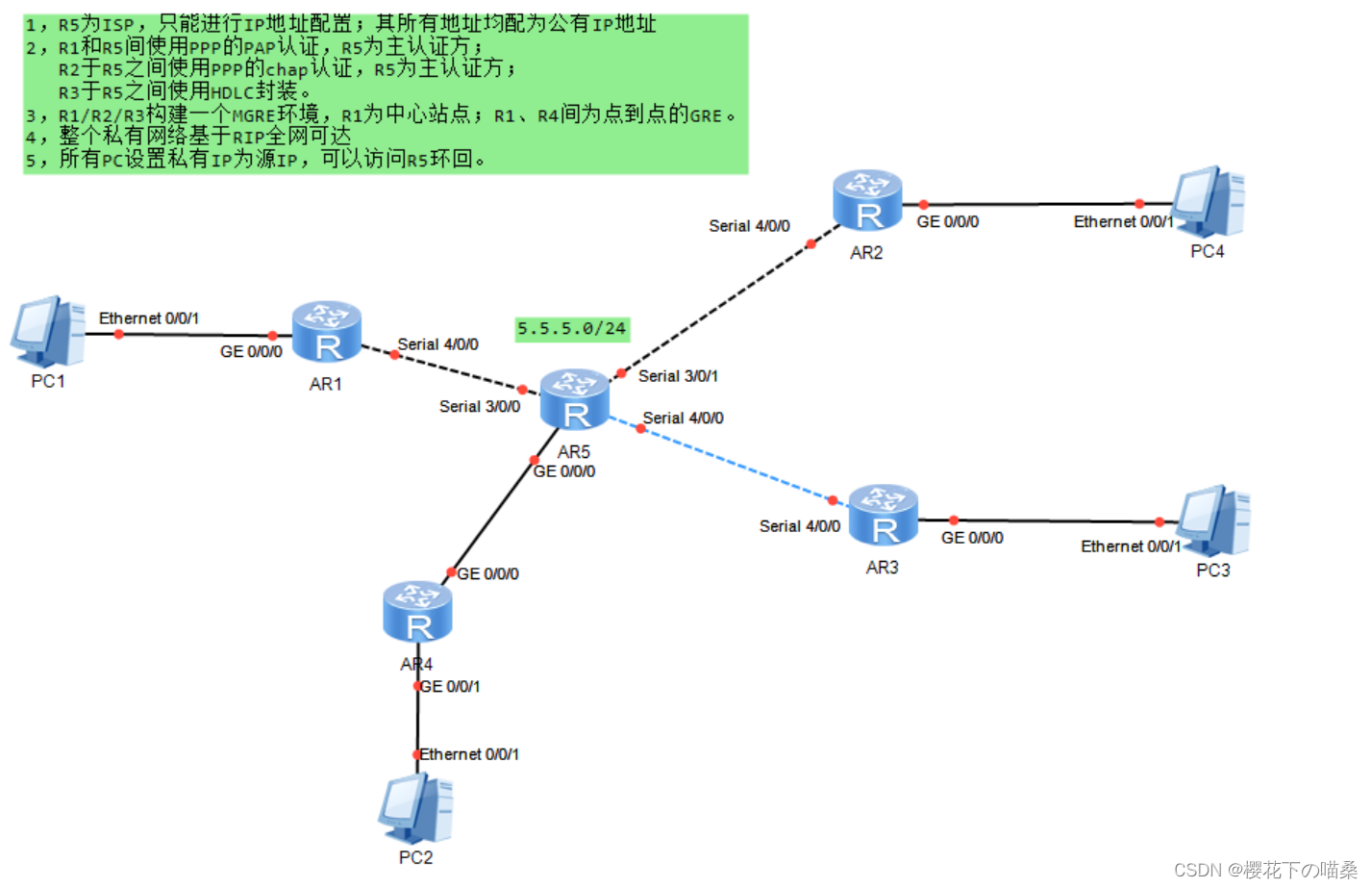
- R5 为ISP,直连网段皆为公网地址IP,其余为私有网段,自行分配,详细见下图。
- R1 和 R5 之间使用
PPP协议的PAP认证,R5 为主认证方 - R2 和 R5 之间使用PPP协议的
CHAP认证,R5 为主认证方 - R3 和 R5 之间使用
HDLC协议封装 - R1、R2、R3之间构建
MGRE环境、R1为中心站点NHS;R1、R4之间构建点到点的GRE环境 - 路由基于
RIP获取 - 私有地址访问公有地址,在R1-R5上配置
NAT
二、操作过程
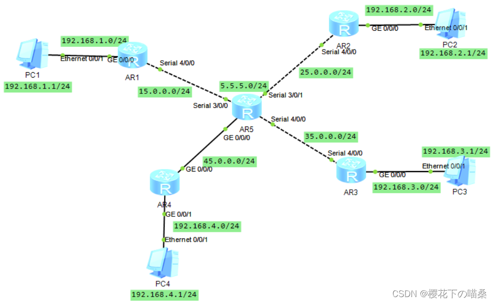
1. 配置IP地址
配置路由器、PC的IP地址及R5的环回
命令
[R1]int g 0/0/0
[R1-GigabitEthernet0/0/0]ip add 192.168.1.254 24
[R1-GigabitEthernet0/0/0]int s 4/0/0
[R1-Serial4/0/0]ip add 15.0.0.1 24

[R2]int g0/0/0
[R2-GigabitEthernet0/0/0]ip add 192.168.2.254 24
[R2-GigabitEthernet0/0/0]int s 4/0/0
[R2-Serial4/0/0]ip add 25.0.0.1 24

[R3]int g 0/0/0
[R3-GigabitEthernet0/0/0]ip add 192.168.3.254 24
[R3-GigabitEthernet0/0/0]int s 4/0/0
[R3-Serial4/0/0]ip add 35.0.0.1 24

[R4]int g 0/0/0
[R4-GigabitEthernet0/0/0]ip add 45.0.0.1 24
[R4-GigabitEthernet0/0/0]int g 0/0/1
[R4-GigabitEthernet0/0/1]ip add 192.168.4.254 24

[R5]int s 3/0/0
[R5-Serial3/0/0]ip add 15.0.0.2 24
[R5-Serial3/0/0]int s 3/0/1
[R5-Serial3/0/1]ip add 25.0.0.2 24
[R5-Serial3/0/1]int s 4/0/0
[R5-Serial4/0/0]ip add 35.0.0.2 24
[R5-Serial4/0/0]int g 0/0/0
[R5-GigabitEthernet0/0/0]ip add 45.0.0.2 24
[R5-GigabitEthernet0/0/0]int l 0
[R5-LoopBack0]ip add 5.5.5.5 24
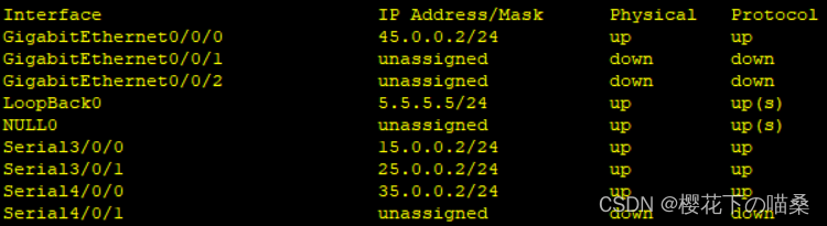
- 查看接口IP地址是否有错误地方,也可以网段内互ping测试
[R5]display ip interface brief
2. PAP认证
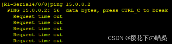
R1 和 R5 之间使用PPP协议封装的PAP认证,R5 为主认证方
命令
主认证方R5配置:
[R5-aaa]local-user admin password cipher 123456  //进入AAA模式创建用户名和密码
[R5-aaa]local-user admin service-type ppp  //定义该用户服务于的协议
[R5-aaa]int s 3/0/0
[R5-Serial3/0/0]ppp authentication-mode pap  //在接口上开启PAP认证
被认证方R1配置
[R1-Serial4/0/0]ppp pap local-user admin password cipher 123456  //用于认证的用户名和密码
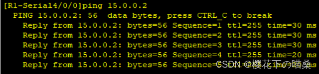
测试
因为PPP会话是一次性会话,不会因为中途配置而中断会话,所以需要重新打开接口测试
[R1-Serial4/0/0]shutdown
[R1-Serial4/0/0]undo shutdown
也可以删除被认证方R1的PAP配置,重新打开接口,测试网络是否通
[R1-Serial4/0/0]undo ppp pap local-user
3. CHAP认证
R2 和 R5 之间使用PPP协议封装的CHAP认证,R5 为主认证方
命令
主认证方R5配置【类似PAP】
[R5]aaa
[R5-aaa]local-user admin2 password cipher 123456
[R5-aaa]local-user admin2 service-type ppp
[R5-aaa]int s 3/0/1
[R5-Serial3/0/1]ppp authentication-mode chap  //接口上开启chap认证
被认证方R2配置
[R2]int s 4/0/0
[R2-Serial4/0/0]ppp chap user admin2
[R2-Serial4/0/0]ppp chap password cipher 123456  //需要分开写
测试- 和pap一样,需要重新开启端口测试
R2 ping R5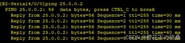
- 和pap一样,需要重新开启端口测试
4. HDLC协议封装
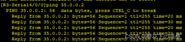
- R3 和 R5 之间使用HDLC协议封装
- 因为华为设备串口默认使用的是ppp协议,所以需要将两端的端口修改为HCLC协议
命令
[R3-Serial4/0/0]link-protocol hdlc

[R5-Serial4/0/0]link-protocol hdlc
测试
R3 ping R5,仅修改一边,是无法互通的
5. 配置GRE环境
- R1、R4之间构建点到点的
GRE环境 - 定义该隧道的网段为192.168.5.0/24,R1的隧道接口IP为192.168.5.1/24 、R4的隧道接口IP为192.168.5.4/24
命令
[R1]int Tunnel 0/0/0  //创建隧道接口
[R1-Tunnel0/0/0]ip add 192.168.5.1 24  //配置虚拟IP地址
[R1-Tunnel0/0/0]tunnel-protocol gre  //定义封装方式
[R1-Tunnel0/0/0]source 15.0.0.1
[R1-Tunnel0/0/0]destination 45.0.0.1  //定义封装内容

R4同理
[R4]int Tunnel 0/0/0
[R4-Tunnel0/0/0]ip add 192.168.5.4 24
[R4-Tunnel0/0/0]tunnel-protocol gre
[R4-Tunnel0/0/0]source 45.0.0.1
[R4-Tunnel0/0/0]destination 15.0.0.1
6. 配置MGRE环境
- R1、R2、R3之间构建
MGRE环境,R1为NFS中心站点 - 定义该隧道的网段为192.168.6.0/24,且R1的隧道接口IP为192.168.6.1/24 、R2的隧道接口IP为192.168.6.2/24 、R3的隧道接口IP为192.168.6.3/24
命令
中心R1配置
[R1]int t 0/0/1  //创建隧道接口
[R1-Tunnel0/0/1]ip add 192.168.6.1 24  //配置IP地址
[R1-Tunnel0/0/1]tunnel-protocol gre p2mp //定义封装方式为点到多点GRE模式
[R1-Tunnel0/0/1]source 15.0.0.1  //定义封装内容,因为目的IP是动态的,所以只写源,该源IP不能改
[R1-Tunnel0/0/1]nhrp network-id 100  //创建域

分支R2配置
[R2]int t 0/0/1  //创建隧道接口
[R2-Tunnel0/0/1]ip add 192.168.6.2 24  //配置IP
[R2-Tunnel0/0/1]tunnel-protocol gre p2mp  //定义封装方式
[R2-Tunnel0/0/1]source Serial 4/0/0  //定义封装内容,使用接口的原因是IP地址可能会变化
[R2-Tunnel0/0/1]nhrp network-id 100  //加入域
[R2-Tunnel0/0/1]nhrp entry 192.168.6.1 15.0.0.1 register //写上中心的隧道接口IP和物理接口IP,相中心注册

分支R3配置【与R2同理】
[R3]int t 0/0/1
[R3-Tunnel0/0/1]ip add 192.168.6.3 24
[R3-Tunnel0/0/1]tunnel-protocol gre p2mp
[R3-Tunnel0/0/1]source s 4/0/0
[R3-Tunnel0/0/1]nhrp network-id 100
[R3-Tunnel0/0/1]nhrp entry 192.168.6.1 15.0.0.1 register
7. 开启RIP动态路由协议
- R1-R4的虚拟接口IP地址,使用192.168.5.0/24网段
- 需要宣告隧道接口网段
- 无需宣告公网地址
- 写一条通往ISP的缺省路由
命令
[R1]ip route-static 0.0.0.0 0 15.0.0.2
[R1]rip 1
[R1-rip-1]v 2
[R1-rip-1]undo summary
[R1-rip-1]network 192.168.1.0
[R1-rip-1]network 192.168.5.0
[R1-rip-1]network 192.168.6.0

[R2]ip route-static 0.0.0.0 0 25.0.0.2
[R2]rip 1
[R2-rip-1]v 2
[R2-rip-1]undo summary
[R2-rip-1]network 192.168.2.0
[R2-rip-1]network 192.168.6.0

[R3]ip route-static 0.0.0.0 0 35.0.0.2
[R3]rip 1
[R3-rip-1]v 2
[R3-rip-1]undo summary
[R3-rip-1]network 192.168.3.0
[R3-rip-1]network 192.168.6.0

[R4]ip route-static 0.0.0.0 0 45.0.0.2
[R4]rip 1
[R4-rip-1]v 2
[R4-rip-1]undo summary
[R4-rip-1]network 192.168.4.0
[R4-rip-1]network 192.168.5.0
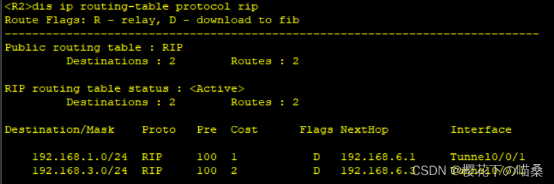
- 路由虽然配置完成,但通过查看RIP路由,会发现除了R1中心站点有路由,R2-R3都没有路由,这是由于RIP初始化状态请求路由表信息的报文是以组播形式发送,而MGRE实质上是一个单播的通信环境,所以需要对NFS的隧道接口上
开启伪广播配置
[R1-Tunnel0/0/1]nhrp entry multicast dynamic
- 就算开启伪广播,分支也只会有R1中心的路由,这是由于RIP的水平分割导致的,所以还需要在NFS隧道接口上
关闭水平分割
[R1-Tunnel0/0/1]undo rip split-horizon
- 再次查看,R2和R3就有路由了
测试
GRE:PC1 ping PC4
MGRE:PC1 ping PC2和PC3
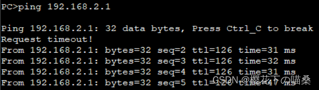 | 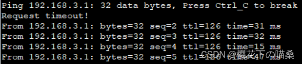 |
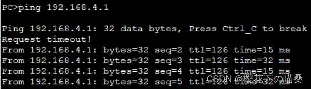
8. NAT配置
- 使用
eazy ip,出接口作为公网地址池 命令
[R1]acl 2000
[R1-acl-basic-2000]rule permit source 192.168.1.0 0.0.0.255  //抓流量
[R1-acl-basic-2000]q
[R1]int Serial 4/0/0
[R1-Serial4/0/0]nat outbound 2000  //调用acl2000

[R2]acl 2000
[R2-acl-basic-2000]rule permit source 192.168.2.0 0.0.0.255
[R2-acl-basic-2000]q
[R2]int s 4/0/0
[R2-Serial4/0/0]nat outbound 2000

[R3]acl 2000
[R3-acl-basic-2000]rule permit source 192.168.3.0 0.0.0.255
[R3-acl-basic-2000]q
[R3]int s 4/0/0
[R3-Serial4/0/0]nat outbound 2000

[R4]acl 2000
[R4-acl-basic-2000]rule permit source 192.168.4.0 0.0.0.255
[R4-acl-basic-2000]q
[R4]int g 0/0/0
[R4-GigabitEthernet0/0/0]nat outbound 2000
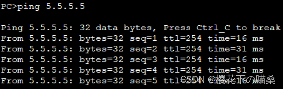
测试
例:用PC1 ping R5 环回


 2230
2230

 被折叠的 条评论
为什么被折叠?
被折叠的 条评论
为什么被折叠?
 到【灌水乐园】发言


