


目录
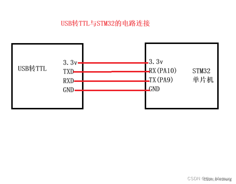
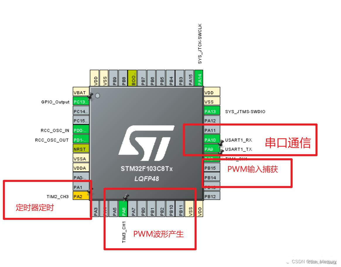
一. 使用STM32F103的 Tim2~Tim5其一定时器的某一个通道pin(与GPIOx管脚复用,见下图),连接一个LED,用定时器计数方式,控制LED以2s的频率周期性地亮-灭。\
二. 接上,采用定时器pwm模式,让 LED 以呼吸灯方式渐亮渐灭,周期为1~2秒,自己调整到一个满意效果。使用Keil虚拟示波器,观察 pwm输出波形。
一. 使用STM32F103的 Tim2~Tim5其一定时器的某一个通道pin(与GPIOx管脚复用,见下图),连接一个LED,用定时器计数方式,控制LED以2s的频率周期性地亮-灭。\
创建文件:
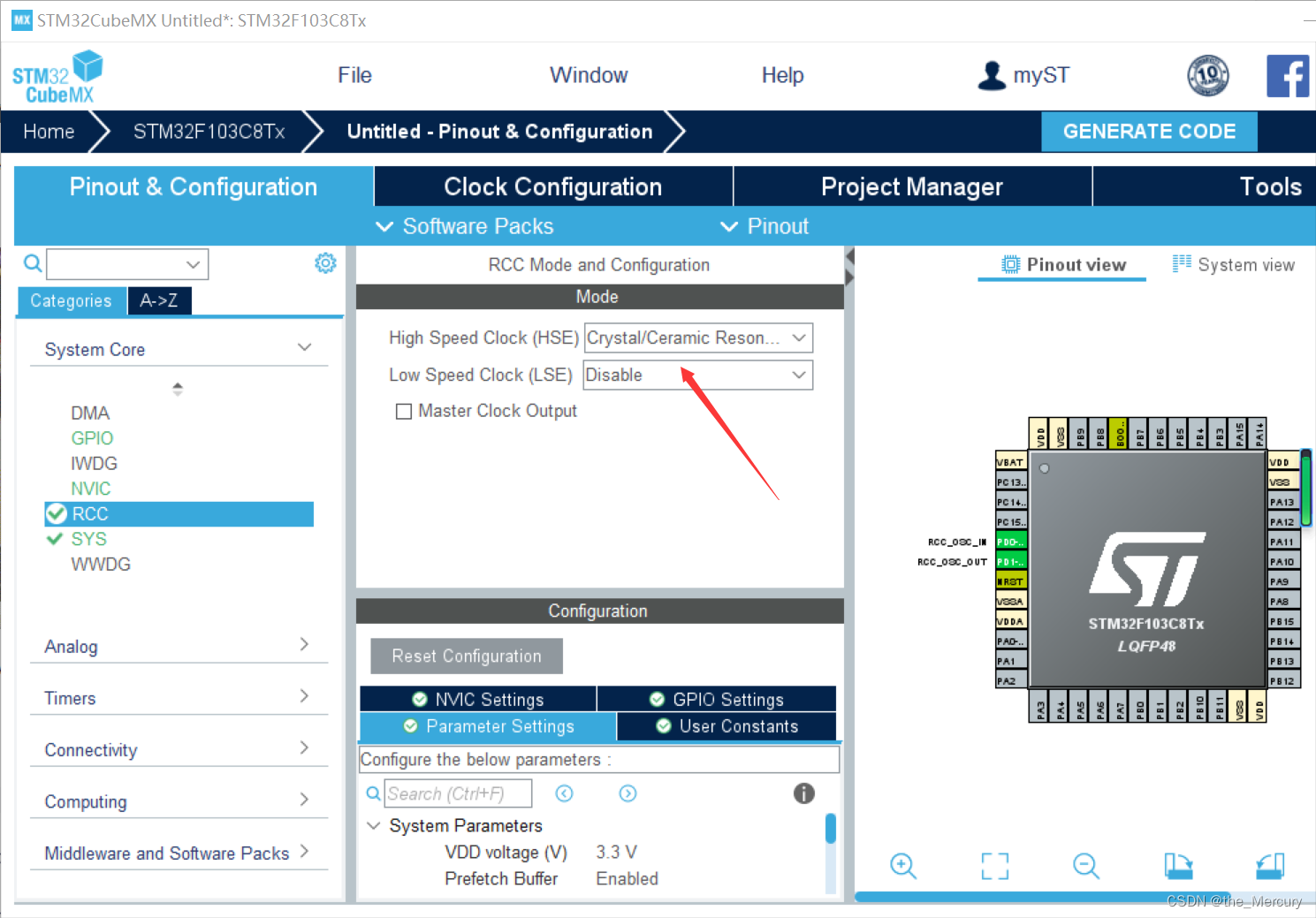
配置RCC
点System Cor,选择RCC,在右侧弹出的菜单栏中选Crystal/Ceramic Resonator

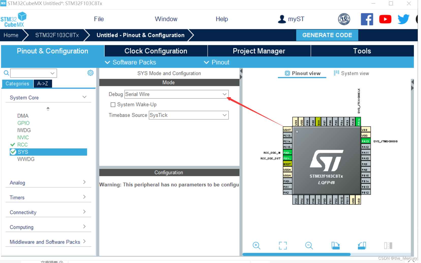
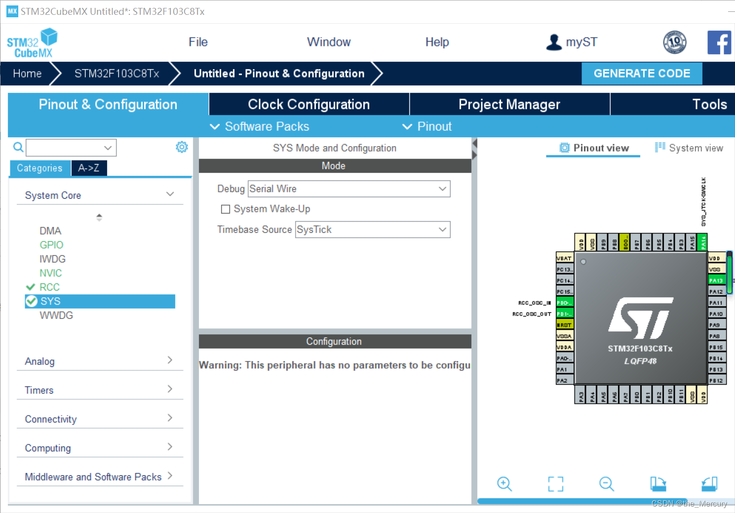
配置SYS
选择调试接口,点System Cor,选择SYS。,在右侧弹出的菜单栏中选Serial Wire。

配置IO口输出
这里选择PA0作为LED灯的输出,将其选为GPIO-OUT,这里我们只使用一个灯,做演示用。

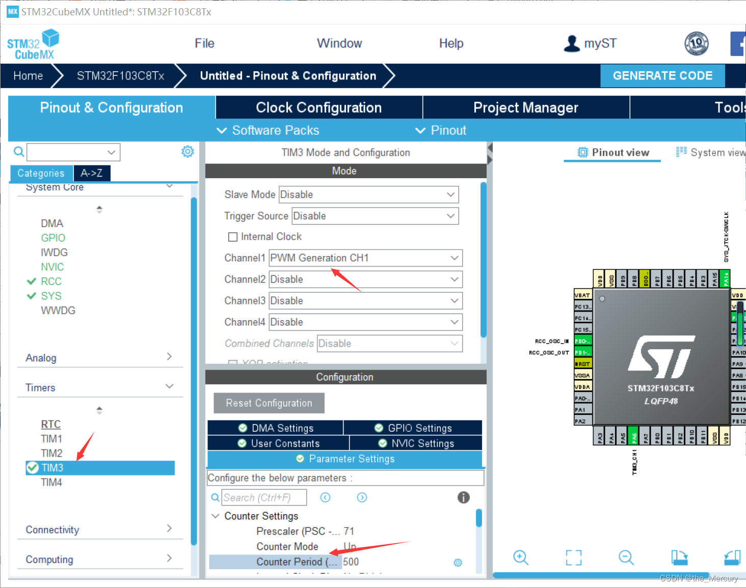
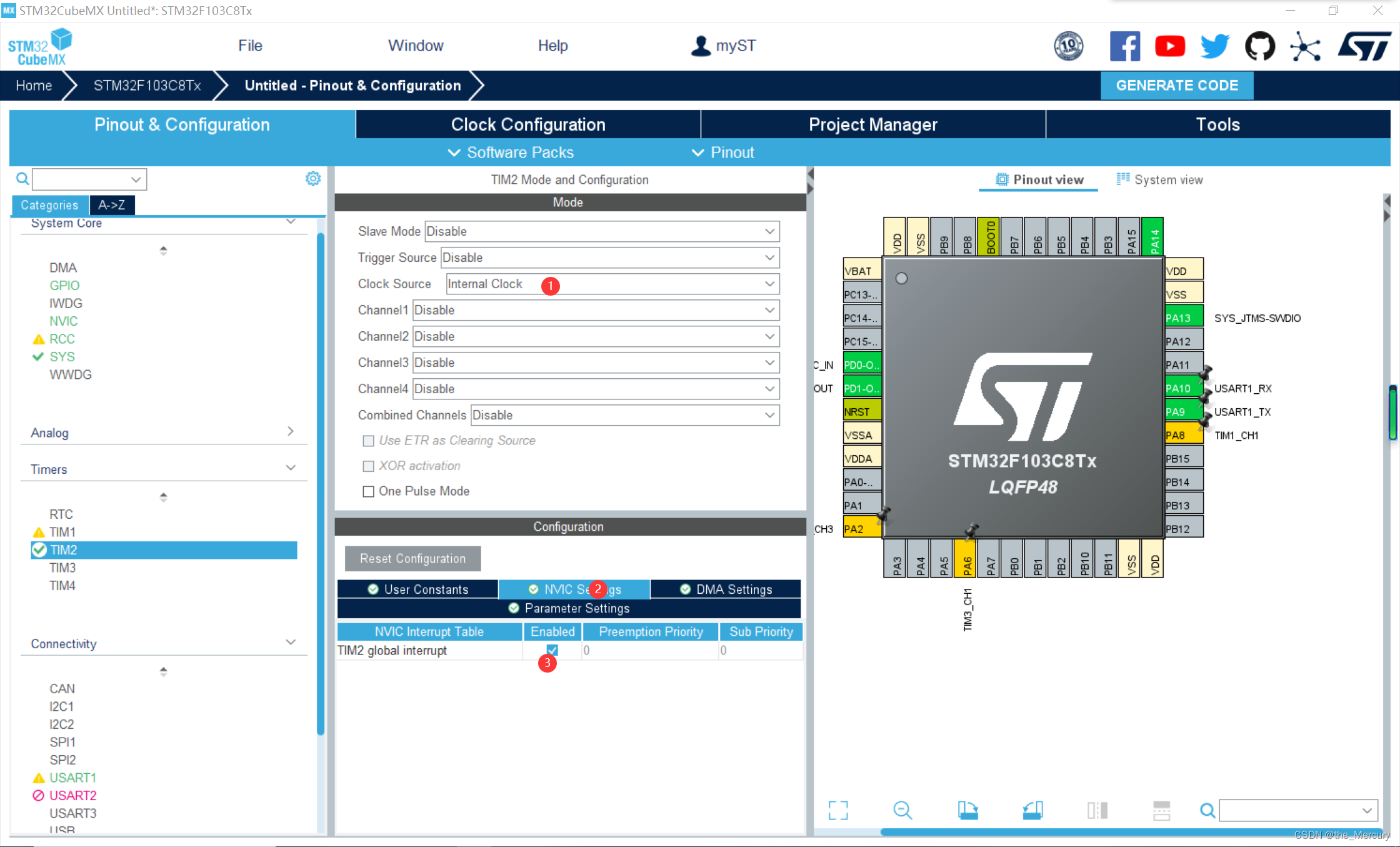
配置定时器2和定时器3
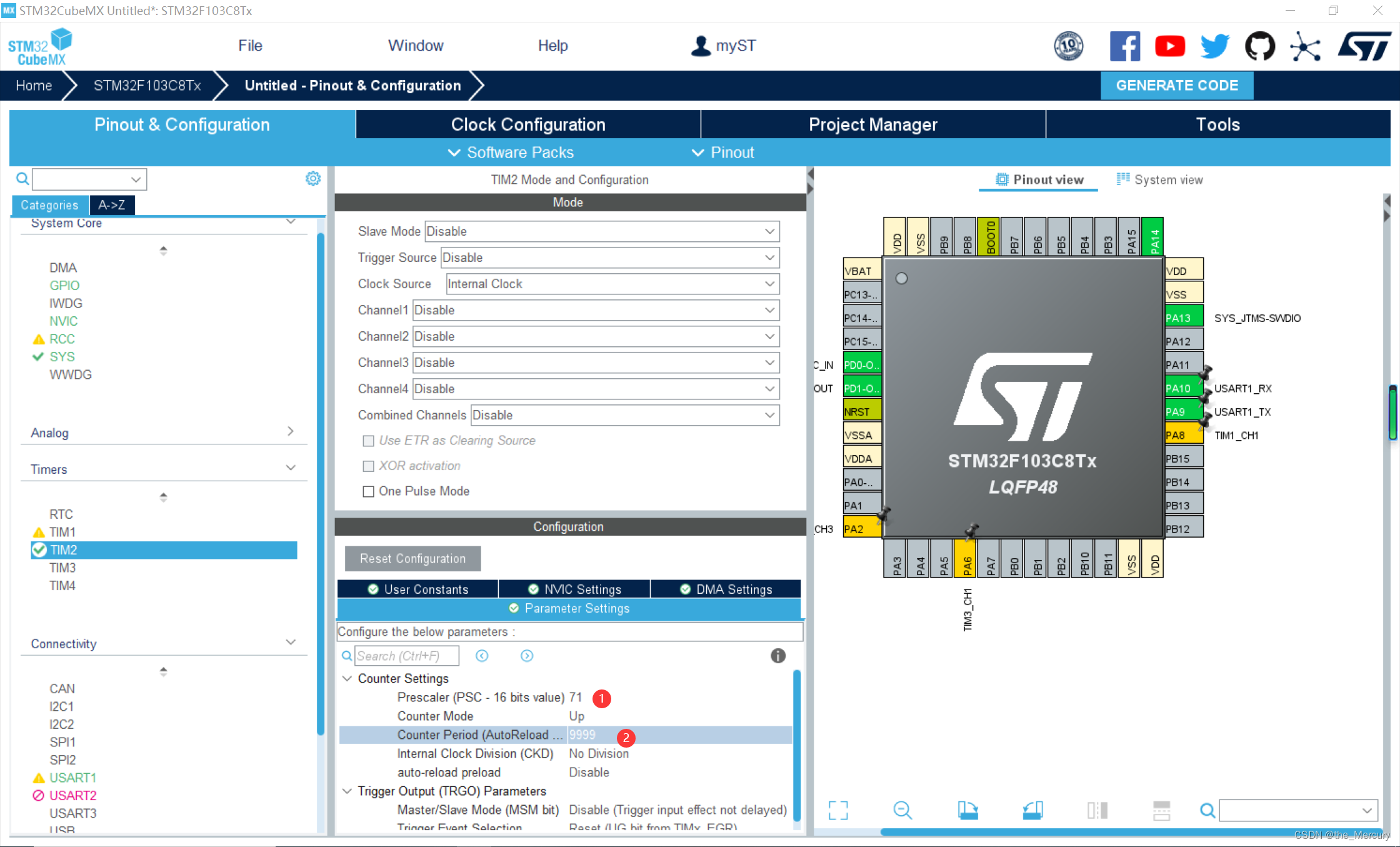
这里我们使用定时器2和定时器3来实现定时的功能。如图所示,定时器2配置:依次点击位置2,选中定时器2;位置3,配置定时器2的时钟源为内部时钟;位置4,分频系数为71;位置5,向上计数模式,计数周期为5000,使能自动重载模式。

定时器3配置:依次按照下图所示进行配置即可:

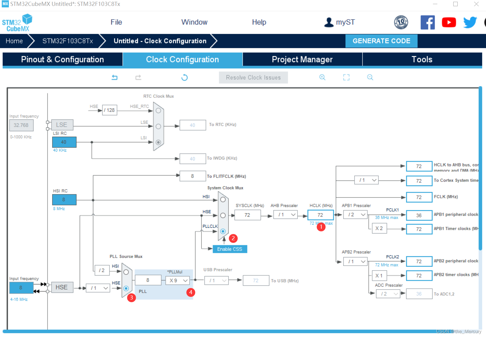
注:分频系数那里虽然写的是71,但系统处理的时候会自动加上1,所以实际进行的是72分频。由于时钟我们一般会配置为72MHZ,所以72分频后得到1MHZ的时钟。1MHZ的时钟,计数5000次,得到时间5000/1000000=0.005秒。也就是每隔0.005秒定时器2会产生一次定时中断。

接着如下图所示,生成定时器2和定时器3中断优先级配置代码:


编辑完成生成文件。
keil部分
(1) 在main.c中添加启动定时器代码:

	HAL_TIM_Base_Start_IT(&htim2);
	HAL_TIM_Base_Start_IT(&htim3);
该函数表示启动相应的定时器,“h”表示HAL库,“tim2”表示定时器2。所以这行代码的意思就是启动定时器2和定时器3。
在main.c中添加定时器中断回调函数:
void HAL_TIM_PeriodElapsedCallback(TIM_HandleTypeDef *htim)
{
    static uint32_t time_cnt =0;
    static uint32_t time_cnt3 =0;
    if(htim->Instance == TIM2)
    {
        if(++time_cnt >= 400)
        {
            time_cnt =0;
            HAL_GPIO_TogglePin(GPIOA,GPIO_PIN_1);
        }
    }
    if(htim->Instance == TIM3)
    {
        if(++time_cnt3 >= 1000)
        {
            time_cnt3 =0;
    HAL_UART_Transmit(&huart1,hello,20,100000);
        }

    }
}
该函数为定时器的中断回调函数,当产生定时中断的时候,会自动调用这个函数。在函数内部定义了定时器的一个静态变量:time_cnt与定时器3 的time_cnt3。
例如time_cnt,当它大于等于100的时候,才会执行if里面的代码。也就是说需要发生400次中断,才会让LED的状态翻转。前面已经算过了,一次定时中断的时间是0.005秒,所以400次中断的时间是0.005400=2秒。也就是说每隔2秒,LED的状态翻转一次。
例如time_cnt3,当它大于等于1000的时候,才会执行if里面的代码。也就是说需要发生1000次中断,才会让串口发一次消息。0.0051000=5秒,符合题目要求。
修改main代码为:
/* USER CODE BEGIN Header */
/**
  ******************************************************************************
  * @file           : main.c
  * @brief          : Main program body
  ******************************************************************************
  * @attention
  *
  * Copyright (c) 2022 STMicroelectronics.
  * All rights reserved.
  *
  * This software is licensed under terms that can be found in the LICENSE file
  * in the root directory of this software component.
  * If no LICENSE file comes with this software, it is provided AS-IS.
  *
  ******************************************************************************
  */
/* USER CODE END Header */
/* Includes ------------------------------------------------------------------*/
#include "main.h"
#include "tim.h"
#include "usart.h"
#include "gpio.h"

/* Private includes ----------------------------------------------------------*/
/* USER CODE BEGIN Includes */

/* USER CODE END Includes */

/* Private typedef -----------------------------------------------------------*/
/* USER CODE BEGIN PTD */

/* USER CODE END PTD */

/* Private define ------------------------------------------------------------*/
/* USER CODE BEGIN PD */
/* USER CODE END PD */

/* Private macro -------------------------------------------------------------*/
/* USER CODE BEGIN PM */

/* USER CODE END PM */

/* Private variables ---------------------------------------------------------*/

/* USER CODE BEGIN PV */

/* USER CODE END PV */

/* Private function prototypes -----------------------------------------------*/
void SystemClock_Config(void);
static void MX_NVIC_Init(void);
/* USER CODE BEGIN PFP */

/* USER CODE END PFP */

/* Private user code ---------------------------------------------------------*/
/* USER CODE BEGIN 0 */

/* USER CODE END 0 */

/**
  * @brief  The application entry point.
  * @retval int
  */
  uint8_t hello[20]="hello windows!\r\n";
int main(void)
{
  /* USER CODE BEGIN 1 */

  /* USER CODE END 1 */

  /* MCU Configuration--------------------------------------------------------*/

  /* Reset of all peripherals, Initializes the Flash interface and the Systick. */
  HAL_Init();

  /* USER CODE BEGIN Init */

  /* USER CODE END Init */

  /* Configure the system clock */
  SystemClock_Config();

  /* USER CODE BEGIN SysInit */

  /* USER CODE END SysInit */

  /* Initialize all configured peripherals */
  MX_GPIO_Init();
  MX_TIM2_Init();
  MX_TIM3_Init();
  MX_USART1_UART_Init();

  /* Initialize interrupts */
  MX_NVIC_Init();
	HAL_TIM_Base_Start_IT(&htim2);
	HAL_TIM_Base_Start_IT(&htim3);

  /* USER CODE BEGIN 2 */

  /* USER CODE END 2 */

  /* Infinite loop */
  /* USER CODE BEGIN WHILE */
  while (1)
  {
    /* USER CODE END WHILE */

    /* USER CODE BEGIN 3 */
  }
  /* USER CODE END 3 */
}

/**
  * @brief System Clock Configuration
  * @retval None
  */
void SystemClock_Config(void)
{
  RCC_OscInitTypeDef RCC_OscInitStruct = {0};
  RCC_ClkInitTypeDef RCC_ClkInitStruct = {0};

  /** Initializes the RCC Oscillators according to the specified parameters
  * in the RCC_OscInitTypeDef structure.
  */
  RCC_OscInitStruct.OscillatorType = RCC_OSCILLATORTYPE_HSE;
  RCC_OscInitStruct.HSEState = RCC_HSE_ON;
  RCC_OscInitStruct.HSEPredivValue = RCC_HSE_PREDIV_DIV1;
  RCC_OscInitStruct.HSIState = RCC_HSI_ON;
  RCC_OscInitStruct.PLL.PLLState = RCC_PLL_ON;
  RCC_OscInitStruct.PLL.PLLSource = RCC_PLLSOURCE_HSE;
  RCC_OscInitStruct.PLL.PLLMUL = RCC_PLL_MUL9;
  if (HAL_RCC_OscConfig(&RCC_OscInitStruct) != HAL_OK)
  {
    Error_Handler();
  }

  /** Initializes the CPU, AHB and APB buses clocks
  */
  RCC_ClkInitStruct.ClockType = RCC_CLOCKTYPE_HCLK|RCC_CLOCKTYPE_SYSCLK
                              |RCC_CLOCKTYPE_PCLK1|RCC_CLOCKTYPE_PCLK2;
  RCC_ClkInitStruct.SYSCLKSource = RCC_SYSCLKSOURCE_PLLCLK;
  RCC_ClkInitStruct.AHBCLKDivider = RCC_SYSCLK_DIV1;
  RCC_ClkInitStruct.APB1CLKDivider = RCC_HCLK_DIV2;
  RCC_ClkInitStruct.APB2CLKDivider = RCC_HCLK_DIV1;

  if (HAL_RCC_ClockConfig(&RCC_ClkInitStruct, FLASH_LATENCY_2) != HAL_OK)
  {
    Error_Handler();
  }
}

/**
  * @brief NVIC Configuration.
  * @retval None
  */
static void MX_NVIC_Init(void)
{
  /* TIM2_IRQn interrupt configuration */
  HAL_NVIC_SetPriority(TIM2_IRQn, 0, 0);
  HAL_NVIC_EnableIRQ(TIM2_IRQn);
  /* TIM3_IRQn interrupt configuration */
  HAL_NVIC_SetPriority(TIM3_IRQn, 0, 0);
  HAL_NVIC_EnableIRQ(TIM3_IRQn);
}

/* USER CODE BEGIN 4 */
void HAL_TIM_PeriodElapsedCallback(TIM_HandleTypeDef *htim)
{
	static uint32_t time_cnt =0;
	static uint32_t time_cnt3 =0;
	if(htim->Instance == TIM2)
	{
		if(++time_cnt >= 400)
		{
			time_cnt =0;
			HAL_GPIO_TogglePin(GPIOA,GPIO_PIN_0);
		}
	}
	if(htim->Instance == TIM3)
	{
		if(++time_cnt3 >= 1000)
		{
			time_cnt3 =0;
    HAL_UART_Transmit(&huart1,hello,20,100000);
		}

	}
}

/* USER CODE END 4 */
/**
  * @brief  This function is executed in case of error occurrence.
  * @retval None
  */
void Error_Handler(void)
{
  /* USER CODE BEGIN Error_Handler_Debug */
  /* User can add his own implementation to report the HAL error return state */
  __disable_irq();
  while (1)
  {
  }
  /* USER CODE END Error_Handler_Debug */
}

#ifdef  USE_FULL_ASSERT
/**
  * @brief  Reports the name of the source file and the source line number
  *         where the assert_param error has occurred.
  * @param  file: pointer to the source file name
  * @param  line: assert_param error line source number
  * @retval None
  */
void assert_failed(uint8_t *file, uint32_t line)
{
  /* USER CODE BEGIN 6 */
  /* User can add his own implementation to report the file name and line number,
     ex: printf("Wrong parameters value: file %s on line %d\r\n", file, line) */
  /* USER CODE END 6 */
}
#endif /* USE_FULL_ASSERT */
烧录结果
二. 接上,采用定时器pwm模式,让 LED 以呼吸灯方式渐亮渐灭,周期为1~2秒,自己调整到一个满意效果。使用Keil虚拟示波器,观察 pwm输出波形。
创建好stm32cube文件
配置rcc文件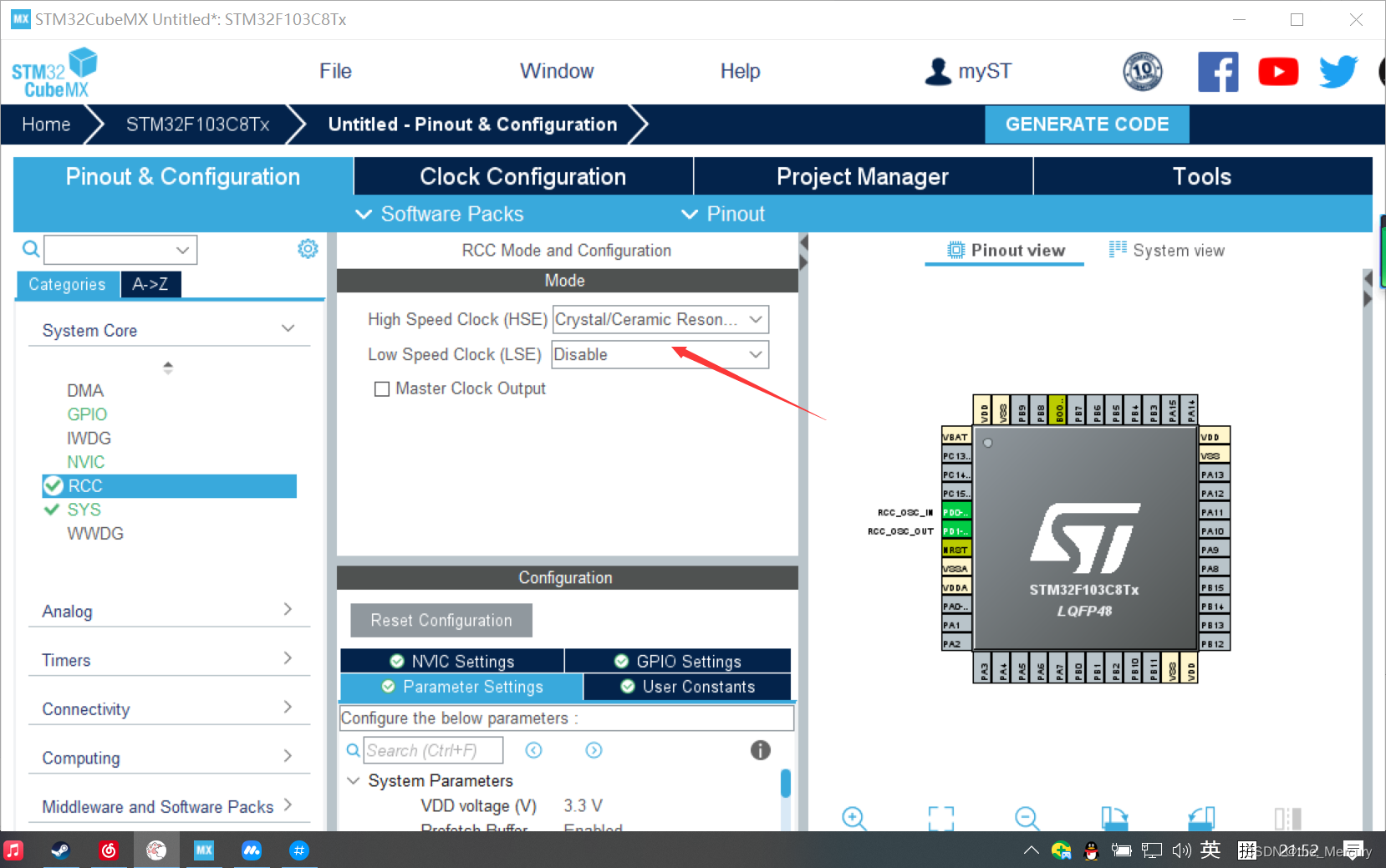
配置SYS
选择调试接口,点System Cor,选择SYS。,在右侧弹出的菜单栏中选Serial Wire。
配置定时器3和定时器4
这里我们选择定时器3和定时器4来实现定时的功位置3,分频系数为71,向上计数模式,计数周期为500,使能自动重载模式。通道1选择:PWM Generation CH1(PWM输出通道1)
设置分频系数为71,计数周期为500,其它默认。
定时器四我们也选择PWM Generation CH1(PWM输出通道1),计数周期根据自己需要进行设置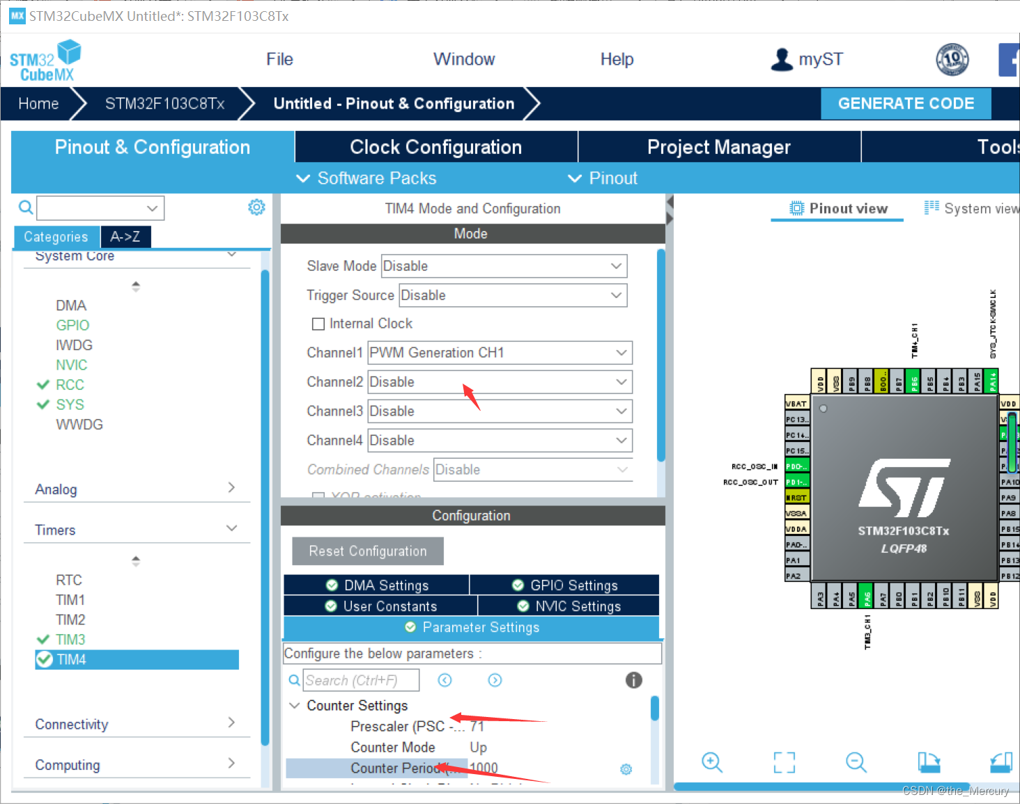
 keil部分
/* USER CODE BEGIN Header */
/**
  ******************************************************************************
  * @file           : main.c
  * @brief          : Main program body
  ******************************************************************************
  * @attention
  *
  * Copyright (c) 2023 STMicroelectronics.
  * All rights reserved.
  *
  * This software is licensed under terms that can be found in the LICENSE file
  * in the root directory of this software component.
  * If no LICENSE file comes with this software, it is provided AS-IS.
  *
  ******************************************************************************
  */
/* USER CODE END Header */
/* Includes ------------------------------------------------------------------*/
#include "main.h"
#include "tim.h"
#include "gpio.h"

/* Private includes ----------------------------------------------------------*/
/* USER CODE BEGIN Includes */

/* USER CODE END Includes */

/* Private typedef -----------------------------------------------------------*/
/* USER CODE BEGIN PTD */

/* USER CODE END PTD */

/* Private define ------------------------------------------------------------*/
/* USER CODE BEGIN PD */

/* USER CODE END PD */

/* Private macro -------------------------------------------------------------*/
/* USER CODE BEGIN PM */

/* USER CODE END PM */

/* Private variables ---------------------------------------------------------*/

/* USER CODE BEGIN PV */

/* USER CODE END PV */

/* Private function prototypes -----------------------------------------------*/
void SystemClock_Config(void);
/* USER CODE BEGIN PFP */

/* USER CODE END PFP */

/* Private user code ---------------------------------------------------------*/
/* USER CODE BEGIN 0 */

/* USER CODE END 0 */

/**
  * @brief  The application entry point.
  * @retval int
  */
  uint16_t duty_num3 = 10;
uint16_t duty_num4 = 10;


int main(void)
{
  /* USER CODE BEGIN 1 */

  /* USER CODE END 1 */

  /* MCU Configuration--------------------------------------------------------*/

  /* Reset of all peripherals, Initializes the Flash interface and the Systick. */
  HAL_Init();

  /* USER CODE BEGIN Init */

  /* USER CODE END Init */

  /* Configure the system clock */
  SystemClock_Config();

  /* USER CODE BEGIN SysInit */

  /* USER CODE END SysInit */

  /* Initialize all configured peripherals */
  MX_GPIO_Init();
  MX_TIM3_Init();
  MX_TIM4_Init();
  	HAL_TIM_PWM_Start(&htim3,TIM_CHANNEL_1);
	HAL_TIM_PWM_Start(&htim4,TIM_CHANNEL_1);

  /* USER CODE BEGIN 2 */

  /* USER CODE END 2 */

  /* Infinite loop */
  /* USER CODE BEGIN WHILE */
  while (1)
  {
    /* USER CODE END WHILE */
        HAL_Delay(50);
		duty_num3 = duty_num3 + 10;
			duty_num4 = duty_num4 + 10;
		if(duty_num3 > 500)
		{
			duty_num3 = 0;
		}
		__HAL_TIM_SetCompare(&htim3,TIM_CHANNEL_1,duty_num3);
			if(duty_num4 > 500)
		{
			duty_num4 = 0;
		}
		__HAL_TIM_SetCompare(&htim4,TIM_CHANNEL_1,duty_num4);
    /* USER CODE BEGIN 3 */
  }
  /* USER CODE END 3 */
}

/**
  * @brief System Clock Configuration
  * @retval None
  */
void SystemClock_Config(void)
{
  RCC_OscInitTypeDef RCC_OscInitStruct = {0};
  RCC_ClkInitTypeDef RCC_ClkInitStruct = {0};

  /** Initializes the RCC Oscillators according to the specified parameters
  * in the RCC_OscInitTypeDef structure.
  */
  RCC_OscInitStruct.OscillatorType = RCC_OSCILLATORTYPE_HSE;
  RCC_OscInitStruct.HSEState = RCC_HSE_ON;
  RCC_OscInitStruct.HSEPredivValue = RCC_HSE_PREDIV_DIV1;
  RCC_OscInitStruct.HSIState = RCC_HSI_ON;
  RCC_OscInitStruct.PLL.PLLState = RCC_PLL_ON;
  RCC_OscInitStruct.PLL.PLLSource = RCC_PLLSOURCE_HSE;
  RCC_OscInitStruct.PLL.PLLMUL = RCC_PLL_MUL9;
  if (HAL_RCC_OscConfig(&RCC_OscInitStruct) != HAL_OK)
  {
    Error_Handler();
  }

  /** Initializes the CPU, AHB and APB buses clocks
  */
  RCC_ClkInitStruct.ClockType = RCC_CLOCKTYPE_HCLK|RCC_CLOCKTYPE_SYSCLK
                              |RCC_CLOCKTYPE_PCLK1|RCC_CLOCKTYPE_PCLK2;
  RCC_ClkInitStruct.SYSCLKSource = RCC_SYSCLKSOURCE_PLLCLK;
  RCC_ClkInitStruct.AHBCLKDivider = RCC_SYSCLK_DIV1;
  RCC_ClkInitStruct.APB1CLKDivider = RCC_HCLK_DIV2;
  RCC_ClkInitStruct.APB2CLKDivider = RCC_HCLK_DIV1;

  if (HAL_RCC_ClockConfig(&RCC_ClkInitStruct, FLASH_LATENCY_2) != HAL_OK)
  {
    Error_Handler();
  }
}

/* USER CODE BEGIN 4 */

/* USER CODE END 4 */

/**
  * @brief  This function is executed in case of error occurrence.
  * @retval None
  */
void Error_Handler(void)
{
  /* USER CODE BEGIN Error_Handler_Debug */
  /* User can add his own implementation to report the HAL error return state */
  __disable_irq();
  while (1)
  {
  }
  /* USER CODE END Error_Handler_Debug */
}

#ifdef  USE_FULL_ASSERT
/**
  * @brief  Reports the name of the source file and the source line number
  *         where the assert_param error has occurred.
  * @param  file: pointer to the source file name
  * @param  line: assert_param error line source number
  * @retval None
  */
void assert_failed(uint8_t *file, uint32_t line)
{
  /* USER CODE BEGIN 6 */
  /* User can add his own implementation to report the file name and line number,
     ex: printf("Wrong parameters value: file %s on line %d\r\n", file, line) */
  /* USER CODE END 6 */
}
#endif /* USE_FULL_ASSERT */
这次灯接的位置为p6
烧录结果
3.定时器pwm完成呼吸灯和对于pwm输出信号的采集与捕获
HEL部分
1.配置rcc
配置SYS
选择调试接口,点System Cor,选择SYS。,在右侧弹出的菜单栏中选Serial Wire。
串口通信配置,如下图所示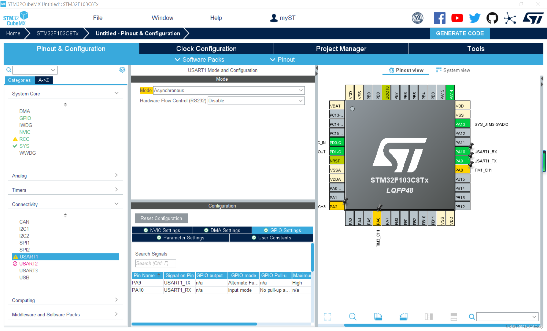
定时器定时配置(TIM2),按照图中步骤进行配置即可:
PWM波形捕获(TIM1)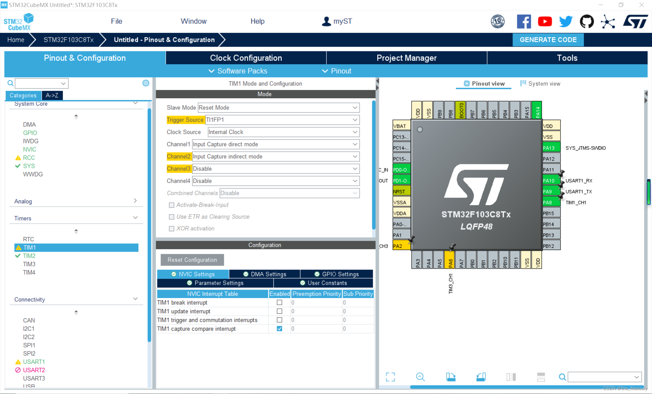
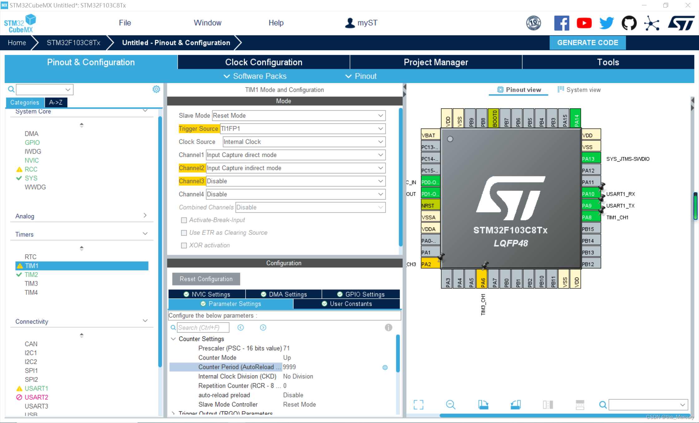
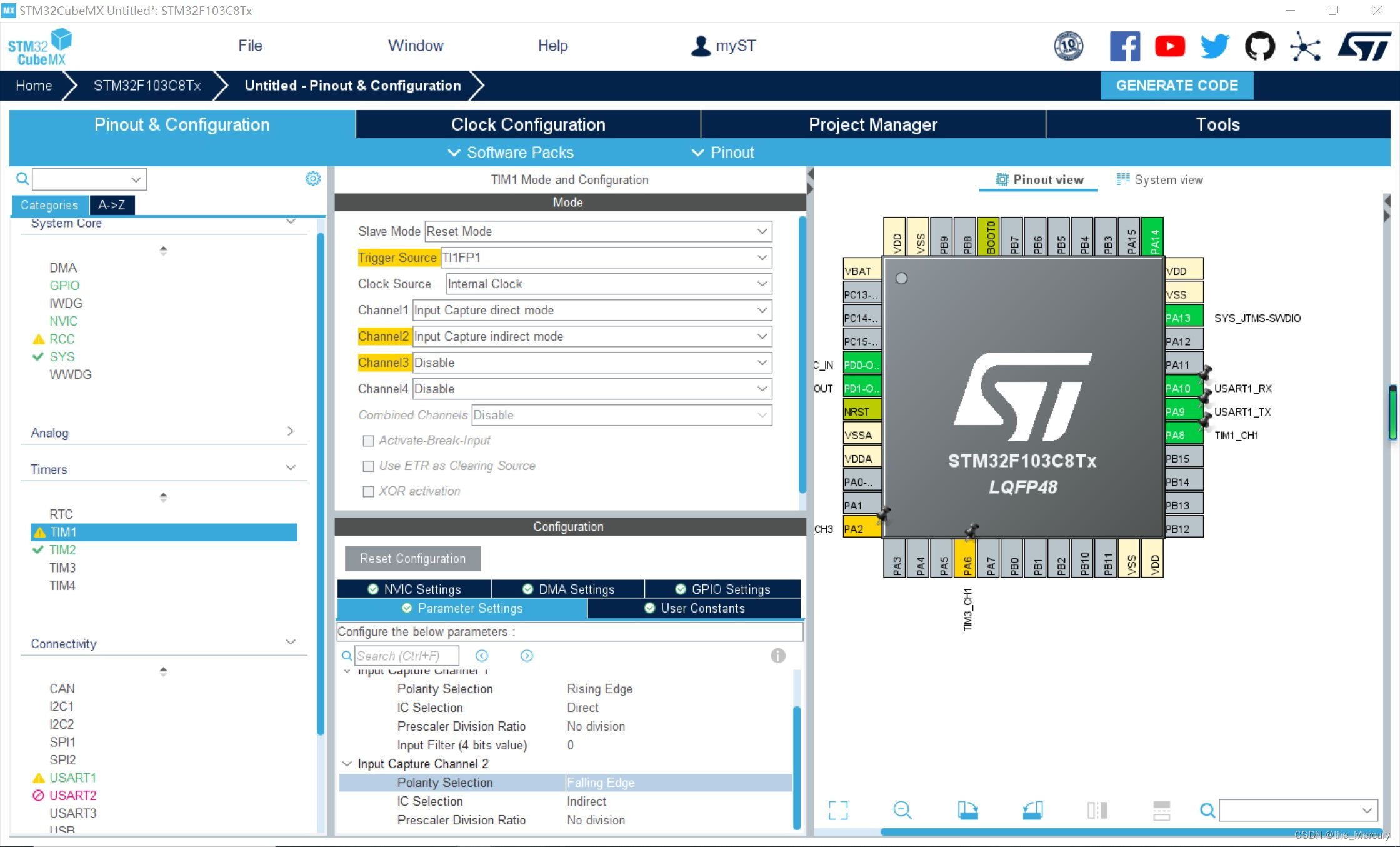
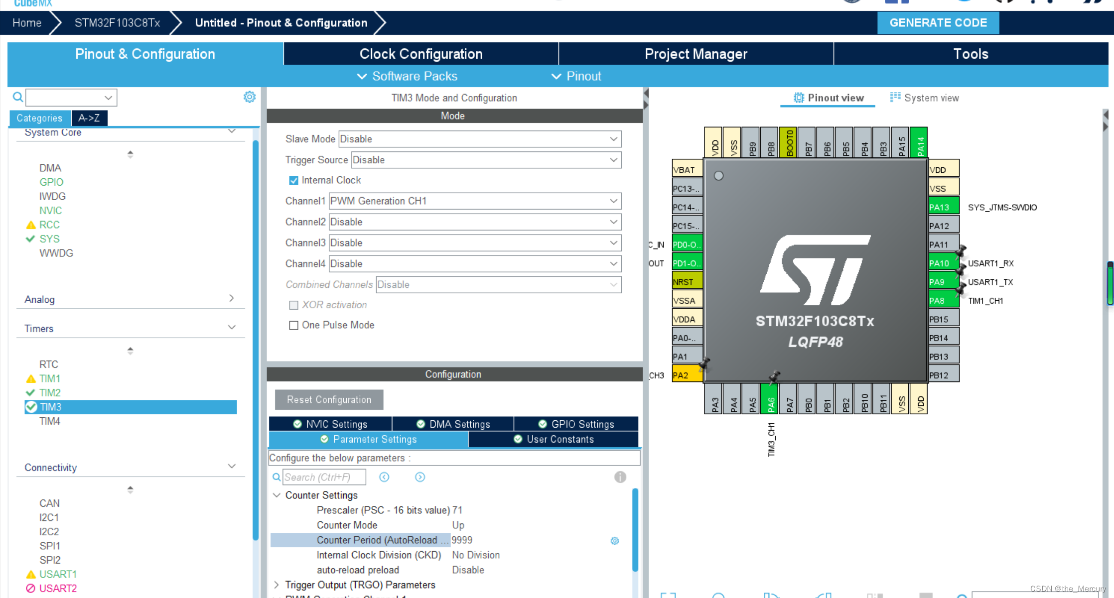
PWM生成配置(TIM3)
完善keil工程:
完善之后的完整main.c代码如下:
#include "main.h"
#include "tim.h"
#include "usart.h"
#include "gpio.h"

uint8_t i = 0;

float Duty = 0;
float Frequency = 0;
uint16_t Cap_val1 = 0;
uint16_t Cap_val2 = 0;

int main(void)
{
    HAL_Init();
    SystemClock_Config();
    MX_GPIO_Init();
    MX_TIM1_Init();
    MX_TIM3_Init();
    MX_USART1_UART_Init();
    MX_TIM2_Init();
    /* USER CODE BEGIN WHILE */

    printf("串口通信测试\r\n");
    HAL_TIM_Base_Start_IT(&htim2); // 使能定时器及其更新中断
    HAL_TIM_PWM_Start(&htim3, TIM_CHANNEL_1); // 使能定时器及其PWM输出
    HAL_TIM_IC_Start_IT(&htim1, TIM_CHANNEL_1);       // 使能定时器及其输入捕获
    HAL_TIM_IC_Start_IT(&htim1, TIM_CHANNEL_2);       // 使能定时器及其输入捕获
    __HAL_TIM_SET_COMPARE(&htim3, TIM_CHANNEL_1, 10); // 设置一个PWM波形进行测量

    while (1)
    {
        // 串口发送 频率 占空比
        printf("Cap_val1 is :%d ,  Cap_val2 is : %d \r\n", Cap_val1, Cap_val2);
        printf("Duty is :%0.2f%% Frequency is : %0.2f ms\r\n", Duty, Frequency);
        HAL_Delay(1000);
    }
}


// 定时TIM2 定时亮灯的中断函数
void HAL_TIM_PeriodElapsedCallback(TIM_HandleTypeDef *tim)
{
    if (tim == &htim2)
    {
        HAL_GPIO_TogglePin(GPIOC, GPIO_PIN_13);
    }
}

// 定时输入捕获回调函数 计算占空比和频率
void HAL_TIM_IC_CaptureCallback(TIM_HandleTypeDef *htim)
{
    if (htim->Instance == TIM1)
    {
        if (htim->Channel == HAL_TIM_ACTIVE_CHANNEL_1)
        {
            Cap_val1 = HAL_TIM_ReadCapturedValue(htim, TIM_CHANNEL_1);
        }
        if (htim->Channel == HAL_TIM_ACTIVE_CHANNEL_2)
        {
            Cap_val2 = HAL_TIM_ReadCapturedValue(htim, TIM_CHANNEL_2);
            Duty = 100 - (float)Cap_val2 / (float)Cap_val1 * 100;
            Frequency = 0.001 * Cap_val1;
        }
    }
}
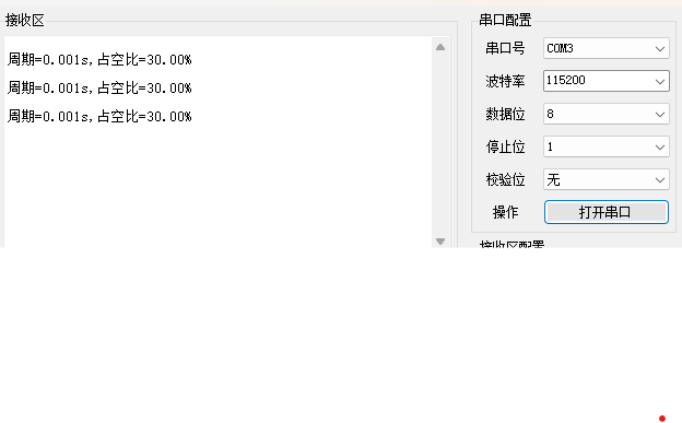
结果
总结:
一. 要实现控制LED以2s的频率周期性地亮灭,可以使用STM32的定时器来计数,并通过比较器控制LED的状态。首先,配置定时器的时钟源和分频系数,选择计数模式为向上计数,并设置自动重载值,以实现周期性计数。然后,配置比较器的阈值,使其触发输出脉冲来控制LED的亮灭。最后,通过GPIO配置引脚为复用功能并连接到定时器通道。
二. 为了让LED以呼吸灯方式渐亮渐灭,可以使用PWM模式。首先,配置定时器的时钟源和分频系数,选择计数模式为向上计数,并设置自动重载值。然后,配置定时器通道为PWM输出模式,设置占空比和周期。通过改变占空比和周期的值,可以调整LED的渐亮渐灭效果。使用Keil虚拟示波器可以观察PWM输出波形的变化。
三. 为了采集PWM输出信号的周期和脉宽,并将其输出到串口显示,可以使用另一个定时器通道来捕获PWM输入信号的边沿。首先,配置定时器的时钟源和分频系数,选择计数模式为向上计数,并设置自动重载值。然后,配置定时器通道为输入捕获模式,设置捕获边沿和触发源。在捕获中断中,可以获取捕获寄存器的值,计算出PWM的周期和脉宽,并将其输出到串口显示。


 2798
2798

 被折叠的 条评论
为什么被折叠?
被折叠的 条评论
为什么被折叠?
 到【灌水乐园】发言


