The 74HC595 is a popular and widely used serial to parallel shift register IC which is used in microcontrollers to interface multiple components while just using 3 pins of the parent IC. In this article, we will be going to discuss the 74HC595 its pins, and its working.
What are Shift Registers?
Shift register of n-bits are comprised of n flip-flops which store the state of the register in n-bits. These shift registers can be used for multiple purposes such as converting serial data to parallel, implementing a stack, providing a delay to the circuit or as in our case, to connect more IO pins. The 75HC595 shift register implements serial in parallel out logic.
74HC595 shift register
The 74HC595 shift register is a high speed 8 bit CMOS IC which is popular for its uses in microcontrollers to convert serial to parallel data and interface multiple I/O devices simultaneously. The IC has an operating voltage of 2.0 to 6.0V.
- It is a very cheap device to get and use to your project and have very effective results. Just by using 3 pins of the parent microcontroller you would be able to interface 8 devices through one register IC.
- We can also daisy chain group of 74HC595s to interface unlimited amount of peripherals by using only 3 pins on the main controller which also leaves other pins for more complex tasks.
- However it is to note that the register provide only digital logic and not analog logic. So the peripherals can only be turned on and off and other analog operations cannot be performed.
74HC595 Pin diagram
The register IC consists of total 16 pins. Let's discuss them one by one
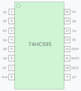
- Pin 15 : Q0 - Parallel data output
- Pins 1 - 7 : Q1 -Q7 - These pins are parallel data output pins which transfers signals to the connected peripherals.
- Pin 8 : GND - Ground pin to ground the circuit.
- Pin 9 : Q7` - Serial data output pin used to send data out serially.
- Pin 10 : SRCLR - This is the master reset pin used in resetting the IC. This pin is active low.
- Pin 11 : SHCP - Shift register clock input, used in synchronizing the clocks.
- Pin 12 : STCP - Storage register clock Input, Used as latch pin.
- Pin 13 : OE - Output Enable pin, This pin is active low.
- Pin 14 : Ds - Serial data Input.
- Pin 16 : Vcc - Positive Supply voltage pin.
Working
- First with data is accepted from pin 14 (Ds) synchronized with the clock.
- With each bit input in the register previous bit shifts to the next slot and the new bit takes position of the previous bit.
- After all the bits enter the register, we pulse the latch pin high and then low to transfer data from shift to storage register
- Now the data is ready to be outputted to the pins Q0-Q7.
Features
- Low power consumption
- Supply voltage of 2.0 to 6.0
- High speed CMOS(Complementary Metal-Oxide-Semiconductor) device
- Separate storage and shift registers
- Can daisy chain multiple 74HC595s
- 3-state output allows multiple devices to share same output lines
Advantages
- You will be able to interface multiple components by using less pin from Arduino
- There is also library support for the shift register in the Arduino IDE
- It is very cheap you can get it in less than 20INR
- Really small in size
- Latching functionality for output control
Disadvantages
- It has limited output control making it unsuitable for high current driving projects
- Complexity in cascading multiple ICs
- It has no input capability, you can only output to external components
- Incompatible with high voltages, its operating voltage is 2V to 6V
How to connect with Arduino?
Connect the following pins to your arduino and 74HC595 IC:
- Pin 14 of the shift register is connected to pin 12 or any digital output pins.(blue)
- Pin 12 of the shift register is connected to pin 11 of the arduino.(yellow)
- Pin 11 of shift register is connected to pin 9 of arduino.(pink)
- Vcc is connected to arduino 5V. (red)
- GND of the register is connected to GND of the arduino. (black)
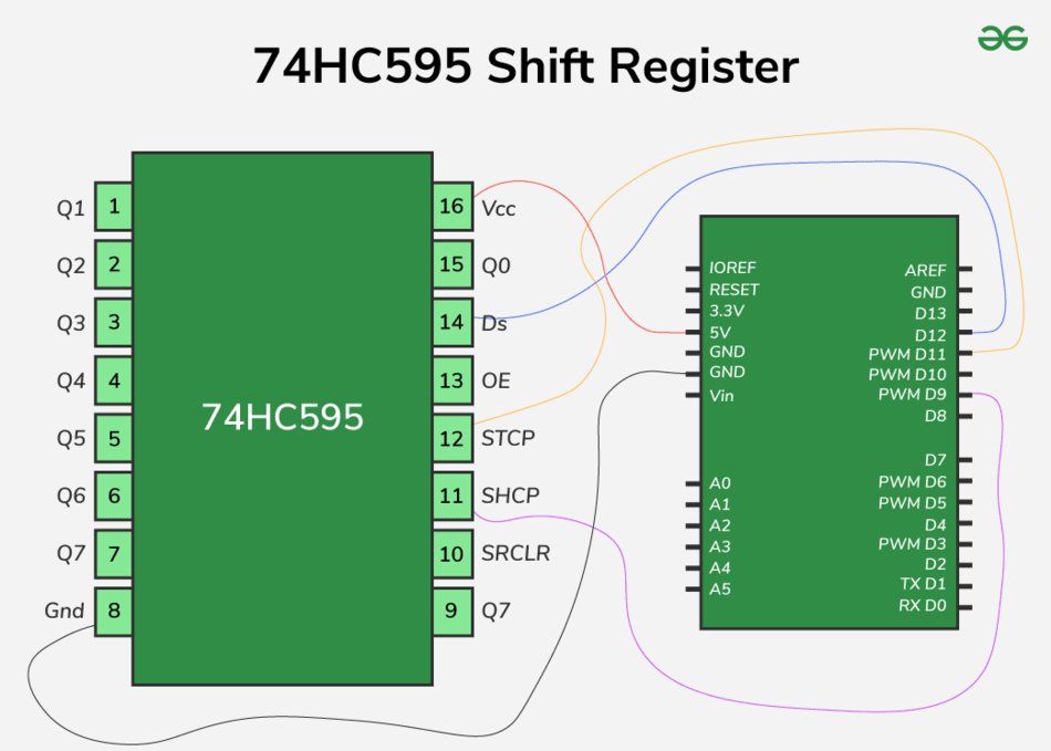
Now your arduino is ready to work and interface multiple devices and control peripherals.
To interface peripherals, just plug them with Q0 to Q7 and pulse input from arduino as hexadecimal numbers using shutout command as shown in the code.
Here is a code Example to turn on 8 LEDs interfaced with 74HC595 register using arduino -
//interfacing 74HC595 w 8 leds

int latch = 11;
int data = 12;
int clock = 9;
byte ledson = 0xFF;  //turn all leds on
byte ledsoff = 0x00;  //turn all leds off
int speed1 = 250;
int speed2 = 250;

void setup() {
  pinMode(latch, OUTPUT);
  pinMode(data, OUTPUT);
  pinMode(clock, OUTPUT);
}

void loop() {
  digitalWrite(latch, LOW);
  shiftOut(data, clock, LSBFIRST, ledson);
  digitalWrite(latch, HIGH);
  delay(speed1);

   digitalWrite(latch, LOW);
  shiftOut(data, clock, LSBFIRST, ledsoff);
  digitalWrite(latch, HIGH);
  delay(speed2);
}

//contributed by shivam mahendru
OUTPUT
Application and Projects
Various simple to complex can be made, with using the shift register. Some of the applications and ideas are -
- Displaying unique and different patterns of 8 LEDs using bitwise and conditional logic.
- Controlling 7 segment display and make a digital clock.
- Home automation control panel.
- Binary counter using LEDs.
- MIDI controller using pushbuttons and potentiometer.
