


There are several nostalgic products that, despite changing our lives for the better, were quietly forgotten due to the constantly evolving tech landscape. In recent times, we've seen CD drives and iPods rise to unprecedented fame before fading into obscurity. But before these gizmos, there was the FM radio, which is far from obsolete even in this day and age!
If you’re a DIY enthusiast who loves retro devices, then you can create an FM radio with the help of a Raspberry Pi. Fair warning, though, it’s quite a complex project involving FM modules, GPIO pins, and jumper cables. So, we’ve compiled a step-by-step guide to help you relive the past by listening to your favorite radio stations straight from your Raspberry Pi.
What you’ll need
Despite being a somewhat advanced project, running an FM radio isn’t all that taxing on the SBC. I’ve used a Raspberry Pi 5 for this tutorial, but you can also go for an older RPi board. That said, you’ll need access to the GPIO pins, meaning owners of certain Raspberry Pi models need to solder these digital signal pins before they can start building the radio.
Next, you’ll require a microSD card where you can store the operating system. Again, you can go for a cheaper, small-capacity card to save some money. We’ll also assume you’ve already flashed the Raspberry Pi OS. If you haven't already set up the flagship RPi operating system, then the overall procedure is the same as installing Ubuntu on the Raspberry Pi. Just be sure to replace the Ubuntu image with the Raspberry Pi OS (64-bit) image when writing the OS files using Balena Etcher.
While we're on the subject, the TEA5767 radio module is another essential component of this project. You’ll find many different TEA5767 boards online, though we’ll use a model that doesn’t require soldering or additional breadboards.
However, since this TEA5767 module doesn’t ship with jumper cables, you’ll have to purchase four female-to-female jumper cables to pair the FM radio module to your Raspberry Pi board. Finally, you must have a headset/speaker with an aux port that you can connect to the radio module.
-
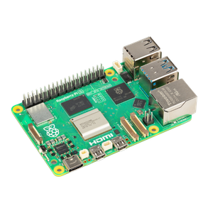
Raspberry Pi 5
- CPU
- Arm Cortex-A76 (quad-core, 2.4GHz)
- Memory
- Up to 8GB LPDDR4X SDRAM
- Operating System
- Raspberry Pi OS (official)
- Ports
- 2× USB 3.0, 2× USB 2.0, Ethernet, 2x micro HDMI, 2× 4-lane MIPI transceivers, PCIe Gen 2.0 interface, USB-C, 40-pin GPIO header
- GPU
- VideoCore VII
- Starting Price
- $60
-
-
-


Connecting the TEA5767 module to the Raspberry Pi
Once you’ve gathered all your components, it’s time to pair the TEA5767 FM radio board to the GPIO pins of your Raspberry Pi.
1. Start by plugging one end of each jumper cable into the pins on the TEA5767 module.

2. Open a pinout diagram of the Raspberry Pi boards on a separate device, like your mobile phone or a PC.

Since most mainline Raspberry Pi boards have GPIO pins in the same location, you can use any diagram for reference.
3. With the help of the pinout diagram, insert the other end of the jumper cables into the Raspberry Pi’s GPIO pins.

Here’s a quick rundown of the cable colors I used: the +5V pin (yellow cable, in my case) on the TEA5767 board connects to pin 4 (5V Power) on the Raspberry Pi. Similarly, the SDA pin (green wire) goes into pin 3 (GPIO 2/SDA), the SLC pin (blue cable) connects to pin 5 (GPIO 3/SCL), and the GND connector (red wire) has to be paired with pin 6 (Ground) on your RPi board.
Pairing the wrong GPIO pins can damage the TEA5767 senser and GPIO pins. In the worst-case scenario, one false connection could even fry your Raspberry Pi. As such, you should exercise extra caution when plugging in the cables.
4. Connect the radio antenna and an audio output device to their respective ports on the TEA5767 module.

5. Plug in the microSD card containing the Raspberry Pi OS, and power on your Raspberry Pi.
If you followed the steps correctly, the blue LED on the TEA5767 module should start glowing.
Enabling the I2C interface in the Raspberry Pi
Now that you’ve physically attached the radio board to the Raspberry Pi, you’ll have to enable the I2C interface to access it on the SBC.
1. Open the terminal app.
2. Launch the Raspberry Pi Configuration Tool by running this command:
sudo raspi-config

3. Navigate to the Interface Options.

4. Select I2C and hit OK when the config tool prompts you to enable the I2C interface.

5. Run the i2cdetect command to ensure the TEA5767 module works with the Raspberry Pi.
i2cdetect -y 1

6. If the terminal displays 60 under row 60 and column 0, then you’ve successfully connected the radio module to your RPi board.
Setting up the Raspberry Pi FM radio
There are a variety of Raspberry Pi-powered radio projects available online, ranging from simple Internet radios that work using Ethernet/Wi-Fi connection to complex projects that require multiple lines of code to be written in C, MicroPython, and other languages.
To keep things simple, we'll go with the Raspberry Pi FM radio repository created by developer Dipto Pratyaksa (LinuxCircle). But before you can start cloning the project, you'll have to install two packages.
1. Fire up the terminal app and install websocket by executing this command:
sudo apt install python3-websocket

2. Clone the Quick2Wire Python API with the help of the git command.
git clone https://github.com/romilly/quick2wire-python-api.git

3. Use the cd command to navigate to the folder where you downloaded Quick2Wire.
cd quick2wire-python-api

4. Install Quick2Wire by running this command:
sudo python3 setup.py install

With websocket and Quick2Wire installed, it's time to install the CLI version of the Raspberry Pi FM receiver.
1. Head back to the Home directory using the cd command.
cd
2. Clone the GitHub repository of the Raspberry Pi FM receiver with the help of the git command.
git clone https://github.com/LinuxCircle/tea5767.git

3. Navigate to the folder where the Raspberry Pi OS downloaded the project files:
cd tea5767

4. Run the tea5767controller.py script by executing this command:
sudo python3 tea5767controller.py

5. Tap the u key to increase the frequency, or press d to go down the frequency range.
6. When you're done, you can press x to close the Raspberry Pi FM receiver and head back to the terminal.
Building a fully-functional Radio-Pi

With that, you're free to experiment with different radio frequencies on your Raspberry Pi-powered FM radio. The TEA5767 module has a frequency range of 76-108MHz, which includes all the important central frequency radio stations in the US and the UK.
But if you've started using the Raspberry Pi for your projects, I suggest starting out with something simple. We have several guides on easy-to-make Raspberry Pi projects, including a tiny stock market price ticker, an all-in-one media server, and a highly secure surveillance system.
