Scout Model 40 is a recording
frequency counter
for the 10 to 1400 MHz frequency range, introduced around 1995 by
Optoelectronics, Inc.
in Fort Lauderdale (FL, USA). The device automatically locks to a
near-field signal that is 15 dB stronger than the current noise level
and stores it in memory.
Scout 40 is based on the original design of the
Scout that was released in 1991.
The device measures just 85 x 66 x 30 mm and weighs 250 grams.
It is powered by internal rechargable NiCd batteries that
can be charged with an external 9 - 12V DC power source.
Despite the limited number of controls, it has many features such as
optical indicator, acoustic indicator, vibrator, variable gate timing,
400 memory positions, etc. It also features reaction tuning,
allowing any AOR-8000 or ICOM CI-V compatible receiver to be tuned
automatically to the frequency detected by the Scout,
using a serial data cable
connected to the data socket.
The first Scout model was developed in 1991 and was covered by US Patent
5,471,402 [1]. It can be used to measure frequencies manually, but can
also detect intermittend transmissions in the vicinity of the device, and
register their frequencies automatically in its 400 position memory.
In addition, it counts the number of hits on each of the stored frequecies,
up to a maximum of 255.
There is also a built-in 16-segment field strength indicator,
that can be used for bug finding.
The device is well built and provides many hours of trouble-free operation
on a single battery charge.
The device and its firmware have been improved and enhanced several
times over the years, but the exterior has remained the same.
Scout Model 40 was still available in 2017, but has since been discontinued.
Support and repair are no longer available from the manufacturer.
The image below provides an overview of the features of the Scout Model 40.
All controls are at the front panel, whilst all connections reside at the
top panel. The device is operated by means of three slide-switches and a
push button, of which the function is printed in white. In addition, the
device can be pwered up in a given mode, as indicated by the functions
printed in blue.
The device is powered by an internal rechargeable NiCd battery pack,
or by an external 9-12V DC source, such as a car battery or a mains
adapter. When using an adapter, the internal batteries are charged.
The Scout can also be connected to a CI-V compatible receiver
for reaction tuning. In that case, the connected receiver will
automatically be tuned to the detected frequency.
Operation
Despite the fact that the Scout 40 has only three slide switches and one
push-button, it is packed with features, most of which can be difficult to
grasp, despite the clear text printed on the front panel. Without access
to the original instructions, some features may never be found.
The function of the switches during normal operation are shown in black.
The function of the switches during the start-up phase of the device
are shown in blue. Finally, the function of the push-button when switching
the device OFF, are shown in red. This is further explained below.
Power up modes
The Scout 40 has several methods of warning the operator when a valid
signal is detected. The position of the switches and the button when
switching it ON, determine the mode of operation.
In addition, the position of the second slide switch when switching ON,
determines whether the backlight of the LCD display will be enabled
or not. It is automatically disabled when not needed.
Communication protocol
The unit supports the ICOM CI-V and the AOR AR-8000 serial communications protocol.
The last selected protocol is always remembered when the device is switched
OFF. Sliding down the third slide switch immediately after turning the unit ON,
selects the alternative protocol:
Controls
Once the unit has been switched ON, the buttons have the following functions:
Gate settings
When in NORMAL or FILTER mode, the gate timing of the frequency counter can
be altered by briefly pressing the GATE push-button. This allows you to cycle
through the four available settings (1-4). The table below shows the timing
and resolution for each of these settings [A].
Note that in capture mode (when frequencies and hits are logged) the gate
timing cannot be altered.
Setting
Gate time
Measurement
Resolution
Example
1
800 µs
8 ms
10 kHz
162.55
MHz
2
8 ms
14 ms
1 kHz
162.550
MHz
3
80 ms
90 ms
100 Hz
162.5500
MHz
4
800 ms
810 ms
10 Hz
162.55000
MHz
Reaction tuning
The Scout has a serial interface that is available on the 2.5 mm jack socket
at the top. This interface can be used for the reaction tuning feature,
and allows a supported receiver to be tuned directly to the captured frequency.
Scout has two protocols for this: CI-V and AR-8000.
The Scout is housed in a metal enclosure that consists of two U-shaped
case shells, fitted to an aluminium frame that consists of top and bottom
panels. By removing four screws from the upper case shell (two at either
side), this shell can be removed, exposing the interior as shown above.
Inside the device are three printed circuit boards (PCBs): the
main board at the bottom,
a display board fitted at its top, and a
signalling board at the bottom. The display board
(also used in other Optoelectronics devices) holds a custom LCD display.
It is fitted to the main board by means of nine pin-contacts,
and can be lifted off.
At the bottom of the display board is a
Philips PCF8576CT universal display controller[a]. The image on the right shows the main board as it becomes visible
after removing the display board. The batteries are fitted below this board.
The main board is specific for the Scout Model 40. It is built around a
Philips P87C524EBAA microcontroller[b] –
a variant of the well-known 80C51 – and a
Xilinx Spartan 3A Field Programmable Gate Array
(FPGA) [c]. The microcontroller is responsible for the user interface
(controls and LCD) and for loading the firmware from its 512KB Read-Only Memory
(ROM) into the FPGA.
The narrow board is connected to the main board by means of 6 contact pins.
Also located below the main board,
is the NiCd battery pack.
It is fitted to the lower case shell by means of double-sided adhesive tape
and is connected to the (+) and (-) terminals on the main board.
When we received the Scout Model 40 featured on this page, the batteries
were exhausted and could not be recharged. Inspection of the interior
revealed that the battery pack had already caused corrosion to the solder
pads on the main board for connection of the battery pack.
Under normal circumstances we would now remove the existing battery pack
and not replace it by a new one. After all, a new battery pack is likely
to degenerate in the future, especially when it is not correctly maintained.
In this case however, we had to replace it, as the Scout cannot be used
at all without a battery pack. The old battery pack was removed and the
solder pads on the main board were thoroughly cleaned. A new battery pack
was then installed and wired again.
Problems
Batteries exhausted and leaking
Fixed
NiCd battery pack replaced
Connections
Power
Scout can be powered by an external 9 to 12V DC power source
such as a 12V car battery or a mains adapter. It is used for powering
the device as well as for charging the internal NiCd battery pack.
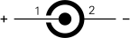
The connector has an outer diameter of 5.5 mm and an inner diameter of
2.1 mm. Below is the pinout when looking into the socket.
PWR
+9V to 12V DC
GND
0V
RF input
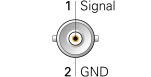
At the top of the device is a BNC socket for the RF input. This can be
a telescopic antenna, a helical antenna (rubber duck) or a cable to an
external antenna. The input impedance is 50Ω
ANT
RF input (50Ω)
GND
0V
Serial port
CIV
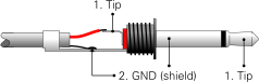
At the top of the device is a 2.5 mm jack socket marked 'CI-V', that
carries a serial port at TTL level (0-5V). It can be used for downloading the
captured data to a Personal Computer (PC),
but also for reaction tuning.
This allows a compatible receiver to be tuned automatically to the
captured frequency. Data format is 9600 baud 8N1.
Below is the pinout of the 2.5 mm jack.