E-1800 is a high-end modular
VLF-HF monitoring receiver
for the 10 kHz to 30 MHz frequency range, introduced in 1985 by
AEG Telefunken (later: DASA)1
in Ulm (Germany), as successor to
the analogue E-1700 range.
Aimed at the military as well as the civil market,
it was intended for surveillance,
radio monitoring, direction finding,
interception and many other applications.
The E-1800 receiver family was known by the Swiss Army and the Swiss Government
as E-663.
The device is housed in a 19" 3U rackmountable enclosure, similar to other
receivers of the era. What makes it stand out from the competition
is that it is modular, and can be configured for a wide variety of applications
by installing a mixture of mandatory and optional plug-in cards.
The device is a labour of love in many aspects.
The front panel is well layed out and operating it is a dream.
Frequency selection is simple and intuitive, and channels can be stored
in the internal memory. Furthermore, stored frequencies can be
scanned at a speed of 140 channels/s. 2
The E-1800 is part of a family of devices of which certain components
could be mixed between models. It is therefore possible that certain
plug-in units have model numbers in the 1700 range, but also in the
1800 and 1810 range. The family comprises the E-1800, E-1900
and E-2000.
The first (analogue) E-1800 model was introduced in 1985 and was considered
in many reviews as one of the best receivers ever produced.
It was followed in 1987 by the E-1800/3
which had an improved front end. In 1994, the range was succeeded by the
E-1800/A, which adds digital signal processing (DSP)
to the design, and offers (optional) waveforms like
QPSK, VSB and pulse modulation.
The E-1900 is the VHF/UHF companion of the E-1800.
It has a frequency range from 20 to 1000 MHz and shares some accessories
and plug-in modules with the E-1800 receiver.
E-1800 · 1985
This is the initial version of the E-1800. It is fully analogue,
except for the synthesizer and the digital readout. The IF-strip
is built with mechanical filters.
The device featured here is largely of this type.
It could be upgraded later with replacement modules.
E-1800/3 · 1987
This is a later version of the E-1800 with an improved
HT-1710 front end.
The rest of the plug-in modules is identical and the receiver
still has mechanical filters in the IF stage. Furthermore,
the speaker and standby switches at the front panel have been altered.
This version is also covered here.
E-1800/A · 1994 - wanted
In this version the 2nd IF stage has been replaced by Digital Signal
Processing (DSP) technology, which enables additional modes, such as
Vestigial Side Band (VSB). The DSP replaces the mechanical
IF filters.
➤ More
Synthesizer
In the basic configuration, the E-1800 and E-1800/3 were supplied with an
AO-1700 analyzer-oscillator, paired with a
SR-1800 or SR-1810/3 memory module. When entering a frequency,
it has a settling time of 100 ms, and allows frequencies to be scanned
at 3 channels per seconds.
The performance of the receiver can be improved by replacing the
AO-1700 with an
SO-1800 or SO-1800/2 synthesizer-oscillator, which has a
frequency settling time of 1 ms and allows scanning up to 140 channels
per second.
According to the 1995 price list, the SO-1800 upgrade was available
for a price of DM 15,680 (EUR 7,840) [4].
The differences are listed in the table below:
Synthesizer
Slow
Fast
Parameter
AO-1700
SO-1800 1
Frequency settling time (with 100 Hz accuracy)
100 ms
1ms
Phase noise (dBc/Hz) Δf = 30 kHz
-140 dB
-120 dB
Phase noise (dBc/Hz) Δf = 300 kHz
-155 dB
-145 dB
Crystal ageing per year
10-6
10-7
Frequency stability
3 · 10-7
2 · 10-8
Search speed (channels/second) 2
3
5-140
The SO-1800 consists of an AO-1710 analyzer-oscillator
paired with an SR-1810 memory card.
➤ More
The search speed depends on the selected bandwidth and the activity on
the selected channel(s), and may also be
affected by the configured communication speed of the
remote control interface.
Below is the front panel of the E-1800. Note that there are many versions
and variants of this device, which is not always obvious from the model
number at the front panel. The front panel is well layed out and the
controls are grouped logically. The unit is switched ON with the toggle
switch at the right. 1 Adjustable controls are at the lower edge.
At the top right are two LED bars: one for showing the signal strength
(right) and a double one that is used as a (FSK) tuning aid.
Below the LED bars are seven push-buttons for selecting the desired
waveform. The buttons are engraved with new style mode names like A1A, J3E,
F3C, B8E, etc., rather than classic names like CW, AM, FM, SSB, FSK, etc.
The desired frequency can be selected with the large rotary dial, but can
also be entered directly on the keypad. The current frequency is shown on
the middle LED display. The rightmost LED display shows the bandwidth,
which can be set in seven steps (max.).
The image above shows the rear side of the E-1800 in the Crypto Museum collection.
Note that there are many possible configurations, depending on the optionally
installed plug-in cards. The E-1800 shown here is a high-end variant,
with a double telegraphy demodulator and — very special —
the SO-1800/2 synthesizer-oscillator. It also has several
IF outputs, a self-test module (BITE) and an
IEEE-488 card for remote control.
In this configuration it is known as E-1800/4.
The device shown here was used for monitoring tasks by the German Army
(Bundeswehr).
On some models the ON/OFF switch is a push-button. Furthermore, its place
may be swapped with the speaker on/off switch.
E-1800/3
The image below shows the front panel of the E-1800/3, which is very similar
but not identical to the one shown above. In particular the area around the
standby and speaker switches at the right is different. Moreover, the labelling
on the seven waveform (mode) push-buttons is different.
The image below shows the rear side of the E-1800/3 in our collection.
The device shown here was used for monitoring and interception tasks in
Switzerland, and was remote controlled via a V.24 (RS232) serial interface.
It has two DE-1710/2 demodulators, allowing the simultaneous
reception of both (independent) side bands.
Uniquely, this variant also has a parallel interface.
Note that the device shown here uses the older AO-1700 synthesizer,
which is much slower.
Single Side Band (USB/LSB) with suppressed carrier
•
R3E
A3A
VSB
Vestigial Side Band, analogue phone
•
H3E
A3H
SSB
Single Side Band (USB/LSB) with full carrier
•
J7B
A7J
SSB
SSB, multiple channels, RTTY
With DE-1710/2 demodulator
•
B7B
A7B
ISB
2-channel RTTY
•
B7D
A7B
ISB
2-channel digital data
•
B8E
A3B
ISB
2-channel analogue phone
•
B9W
A9B
ISB
2-channel combination of analogue and digital signals
With TD-1710 telex demodulator
•
F1B
F1
FSK
Frequency Shift Keying - Radio Teletype (RTTY)
•
F1C
F4
FAX
Facsimile
•
F7B
F6
4-FSK
MFSK-4, channel A only
•
F3E
F3
FM
Narrow Band Frequency Modulation (NBFM)
With additional TZ-1710 telex interface
•
F7B
F6
4-FSK
MFSK-4, both channels (A and B)
Building blocks
The E-1800 consists of a large number of printed circuit boards (PCBs),
held together by means of an aluminium 19" frame with a hand-wired
backplane, all of which are shown in the drawing below. At the front are
the control panel and associated electronics, plus the CPU board,
all of which are fixed in place. The CPU has two expansion slots, one of
which holds the control interface.
All front panel PCBs are mounted in a single sub-frame that is bolted
to the main 19" frame.
At the rear is space for 10 plug-in modules that together form the receiver.
At the far right is an extra panel (11) for the control interface connector.
Some plug-in cards are mutually exclusive.
The slots are numbered 1-10 from left to right, when facing the rear.
Slots 1,4, 5, 7, 9, 10, and 11 have a fixed assignment. The remaining
slots (2, 3, 6, 8) are flexible and are used for optional expansion cards.
In the diagram above they are shown in blue.
Note that units 9a and 9b are bolted together.
Below is an overview of the various modules that can be installed
in each slot.
= in Crypto Museum collection
= documentation available
The IEC-1800 or SER-1800 or PSE-1800
card is an option. It is not installed in a bakcplane slot, but is
connected directly to the (optional) interface that is fitted to the
processor board behind the front panel.
The serial card (SER-1800) can also be used as a second
interface (in addition to the PSE-1800 or IEC-1800
card).
The SR-1800 (or SR-1810/3) memory unit is integrated with the
AO-1700 analyzer-oscillator. The complete construction
(AO-1700 + memory card) uses two backplane slots and occupies the space
for three slots.
The combination of AO-1710/2 and SR-1810 is known as the
SO-1800 synthesizer-oscillator. The two cards are bolted together
but use two separate backplane slots. The assembly occupies the space for
three slots. An E-1800 receiver that has the SO-1800 assembly fitted,
is also known as E-1800/4.
The E-1800 is housed in a 19" 3U rackmountable enclosure,
which offers space for the front panel, the CPU and a range
of plug-in cards, interconnected by a hand-wired backplane,
as shown in the image on the right.
The frame is shown here as seen from the front.
The backplane wiring is just behind the front panel (which is
removed here). At the far
left is a ribbon cable that connects the interface board (installed
on the CPU when present) to the outside world via a panel in slot 11.
That panel also holds the socket for an external speaker.
BF-1800
Control panel
The control panel is fitted to the front of the receiver. It consists
of an aluminium front panel, behind which a
PCB with the controls
is located, as shown in the image on the right.
An additional PCB with the electronics
is fitted behind it.
The Central Processing Unit (CPU) is located behnd the front panel
electronics. It runs over the full width of the receiver and is
connected to the front panel and the backplane. The CPU runs on a 8085
processor, and has two expansion slots in which a eurocard-size PCB
can be fitted.
The CPU shown in the image on the right is fitted with an
(optional) IEC-1800 card.
This allows the radio to be controlled from, say, a computer.
It is also possible to install a V.24 (RS232) serial port, or a parallel
control interface in this position.
The E-1800 is powered by an internal mains power supply unit (PSU),
which is installed in slot 1 (i.e the leftmost slot when viewed from
the rear). It occupies 2 slot spaces.
The PSU can be configured for the 110V or 220V AC mains
voltage, by means of an internal solder strap.
Alternatively, the BS-1800 PSU can be installed in this slot.
It is equivalent to the NS-1800 shown here, but can also be used
to power the device from a 21.5 V to 30 V DC voltage.
The E-1800 can be fitted with the telegraphy (telex) demodulator
shown in the image on the right. It can readily convert a received
Frequency Shift Keying (FSK) signal into a digital telex signal
that can be supplied to a teleprinter.
If necessary, the E-1800 can be fitted with an extra telex demodulator,
so that it can simultaneously demodulate two FSK telex signals sent
in 4-FSK mode (also known as F7B, F6 or MFSK-4).
For the reception of regular phone and CW signals, the DE-1710
demodulator shown in the image on the right is used. It is alsways
fitted in slot 4 and is mandatory.
The card shown here is the DE-1710/2, which is suitable for the
reception of AM, FM, CW or SSB (LSB, USB) signals.
By installing a second DE-1710(/2) card, it is possible to
process ISB signals.
The E-1800 has an Intermediate Frequency (IF) strip with
in-house developed and manufactured mechanical filters that
are installed as plug-ins on the FI-1710 filter board shown
on the right.
Up to 7 mechanical bandwidth filters can be installed,
selectable from this list.
If necessary, the receiver can be fitted with a BA-1700 wideband 10.7 MHz
output card, which is suitable for connection to a panorama display,
such as the PSG-1800.
This card must be installed in slot 6, but is mutually exclusive
with the ES-1700 preselector.
HT-1710/2
RF unit
The HT-1710 RF-unit, or front-end, is mandatory and should be placed
in slot 7. It has two antenna inputs: one for the 10 kHz to 1.6 MHz range
and one for 1.6 to 30 MHz, which can optionally be
combined into one input.
The image on the right shows the HT-1710/2 version of the RF-unit. Its
compartmented design consists of three PCBs, comprising the RF front-end,
the IF1 stage and the IF2 stage. The middle PCB is further
divided into 4 compartments by means of silver plated metal panels.
Slot 8 is reserved for optional expansion cards. It accepts the FU-1800 frequency
converter shown here. It serves two purposes:
(1) It provides an IF-output at 30 or 525 kHz, selectable with a
switch. The signal can be fed directly to an external FSK decoder,
such as the Rohde & Schwarz GA-082 FSK analyzer or
the Teletron TG-44E.
(2) This card also provides a balanced AF line output that can be used
by a recording device (frequency response: 500 Hz - 18 kHz).
Slot 9b is reserved for the AO-1700 analyzer-oscillator, which forms
the heart of the system, as it synthesizes the necessary tuning
frequencies. It occupies two slot spaces and is always paired with
an SR-1800 or SR-1810/3 memory unit in slot 9a.
The assembly takes 3 slot spaces.
Slot 9a is reserved exclusively for the memory card.
The SR-1810/3 is a replacement for the SR-1800.
It is identical to the SR-1810, but is integrated
with the AO-1700 analyzer-oscillator in slot 9b. It also has a
slightly smaller faceplate.
The faceplate of the memory card holds a 50-pin DD50 connector
that gives access to the peripheral bus. It is often used
for connection of a panorama display, such as the
PSG-1800.
Slot 9b can also be used for the AO-1710/2 analyzer-oscillator.
Together with the SR-1810 memory card it forms the SO-1800/2
synthesizer-oscillator. It settles frequency changes in 1 ms, whereas this
took 100 ms on the AO-1700.
The AO-1710/2 comprises three stacked PCBs, plus a
10 MHz reference oscillator
that bulges out at the rear. It can be synchronised externally
or can be used to synchronise other receivers.
The memory board is part of the SO-1800 assembly. It is fitted
in slot 9a and holds CMOS memory in which channels and frequencies are stored.
It is only present when the next slot holds an
AO-1710(/2) analyzer-oscillator.
All internal circuits can be tested automatically by means of
the so-called Built-in Test Equipment (BITE). When present,
this board is fitted in slot 10. After pressing the push-button,
the test runs for several seconds, after which the green LED lights
up. Faults are flagged with a red LED.
The empty space on the BT-1800 can be used for fitting the optional
Digital BFO (circuit), in which
case it is known as BT-1800/2.
The E-1800 can be controlled externally by means of an optional
IEC-625 interface that is installed as a plug-in card on the CPU board,
as shown in the image on the right.
The accompanying connector is fitted in slot 11 and is
connected to the card by means of a ribbon cable.
The IEC-625 card is also known as IEEE-488, GPIB and HPIB.
The German Army (Bundeswehr) used this interface for remote control.
The SER-1810 card allows the E-1800 to be controlled remotely,
as an alternative to the IEC-1800 card shown above. In is intalled
as a plug-in card on the CPU board, and features a V.24 (RS232)
interface that is routed to a DB25 socket at the rear via a
flat cable. The control protocol is fully documented in the manual.
The SER-1810 serial card can also be installed as a second
remote control interface (e.g. in addition to the IEC-1800), in which
case it is placed in the extra slot on the CPU board.
The PSE-1800 card is an alternative to the IEC-1800 and SER-1800
cards, and offers a parallel interface. It is installed as a plug-in
on the CPU board and has a flat cable running to the rear of the
receiver, where a 50-pin DD50 socket is present on a blind panel.
The pinout of the connector is described here.
Note that this connector is of the same type as the connector on the
SR-1810 memory card. To avoid mistakes, there is a pin-coded
mask at either end of the socket and plug.
When we received our E-1800, it was in unknown state. Apparently it had
been collecting dust for quite a few years, as the front panel was barely
recognisable. It is also likely that the device(s) had been thrown around
after they were decommissioned, as the front panel and the frame
were badly damaged at the corners. According to the labels on the front panel,
the device had been used by the German Army (Bundeswehr, BUND).
It was also noticed that it was configured for 115V/AC.
In order to test the device, it was connected to the AC mains via a
VARIAC that was adjusted to produce an output voltage of 110V.
Surprisingly, the device worked straight away and after a short warming up
time, we were able to receive the first signals. Not bad for a receiver
that was manufactured no less than 40 years ago!
The AF gain control appeared to be damaged or broken, as it was difficult
to adjust the audio volume.
In order to clean the device and repair the damages, it was decided to
take it apart completely. This would also give us a chance to inspect
the circuits.
All plug-in cards were removed from the rear side of the rack, and the front
panel assembly — which holds the front panel controls and the CPU — was
detached. The now empty frame was thoroughly cleaned and any damages and
bended corners were repaired carefully. Next, the front panel assembly was
taken apart, so that the front panel could be cleaned and straightened.
The volume potentiometer was repaired and the axle of the frequency dial
was thoroughly cleaned.
The power supply unit (PSU) was converted to 230V and the
electrolytic capacitors were replaced, since one of then was already
bulging out somewhat.
This is generally a sign that the capacitor is about to blow itself up.
Replacing these capacitors appeared to be quite tough,
as they are glued to the PCB.
When inspecting the PSU further, it was noticed that the
so-called X- and Y-capacitors had cracks in them.
Over time, these cracks attract
moisure which eventually may cause the capacitor to explode. We decided
to replace them as a precautionary measure.
Problems
Extremely dirty
Front panel and case frame damaged (corners bended)
PSU configured for 115V AC mains
Cracks spotted in X and Y capacitors in PSU
Low quality internal speaker
Volume control broken
Fixed
Unit completely disassembled
Exterior and interior thoroughly cleaned
Front panel disassembled, cleaned, straightened and reassembled
19" frame straightened, repaired and cleaned
Volume potentiometer repaired
PSU electrolytic capacitors replaced
PSU configured for 230V/AC
Front panel speaker replaced
E-1800/3
29 May 2025
We recently received an E-1800/3 from Switzerland. When it arrived, it was
in working order, but after approx. 20 minutes it suddenly 'died'. After
swapping the PSU with the known-good one from our E-1800, we established that
the problem was indeed caused by the NS-1800 module. After opening it, we
noticed that it was the older version
of the NS-1800 (→ circuit diagram) that does not have
the improved startup circuit (→ later version).
After replacing GR6 and R25, the PSU works again.
As a safety measure, we also replaced all electrolytic capacitors
in the NS-1800.
Depending on the previous use of a (surplus) E-1800 and your personal
wishes, you might want to consider one or more of the modifications described
below.
Convert PSU to 230V
Some PSUs, in particular those of the E-1800 receivers used by the German
Bundeswehr, are configured for 115V/AC, rather than the regular European
voltage of 230V/AC. Fortunately, it is rather simple to convert the
NS-1800 PSU.
➤ More
Extend the lower boundary of the frequency range
German radio amateurs have successfully managed to extend the frequency
range of the E-1800 to below 10 kHz, simply by patching the firmware of
the CPU.
More information can be found ➤ here (off-site)[1].
Replace speaker
The quality of the built-in front panel speaker is not excellent.
It works, but its plastic membrane has disturbing resonances within the audio band.
If you are going to use the receiver with an external speaker, there is nothing
to worry about, but if you want to use the internal one, you might want
to replace it with a proper alternative.
Single antenna input
The E-1800 has two antenna inputs: one for the 10 kHz to 1.6 MHz range,
and one for the 1.6 MHz to 30 MHz range. By altering a strap inside the
HT-1710 front end, the two inputs can be combined.
When the strap is in the 3/4 position,
only the lower antenna socket (10 kHz - 1.6 MHz) should be used.
➤ More
Error messages
Error
Description
Affected card
E01
Control error. No useful function
E02
Entered frequency out of range
E03
Function not available (hardware missing)
E20
No Valid frequency in scan memory.
E21
Error when entering scan parameter FL (out of range)
E22
Error when entering scan parameter FH (out of range)
E23
Error when entering scan parameter dF (dF=0000)
E50
ROM error (checksum error)
E55
RAM error
E57
Control error (only when BT is fitted)
ZS, BF, SR, AO, BT
Interface
E60
Timeout
IEC, SER, PSE
E61
Parity error
IEC, SER, PSE
E62
Overrun
IEC, SER, PSE
E64
DSR error
IEC, SER, PSE
E65
Framing error
IEC, SER, PSE
E66
CTS error (SER), or waiting for IEC bus (IEC)
IEC, SER, PSE
E70
Sensing line BU1 contact 39 low 1
SR
E71
Sensing line BU1 contact 40 low 1
SR
E72
Sensing line BU1 contact 41 low 1
SR
E73
Sensing line BU1 contact 42 low 1
SR
Card error (when BT present)
E80
Power Supply Unit (PSU)
NS, BS
E81
Reference oscillator, temperature out of tolerance 2
AO, ZO
E82
Out of sync
AO, ZO
E83
Level 1 out of tolerance
AO, ZO
E84
Level 2 out of tolerance
AO, ZO
E85
Preselector
ES
E86
RF-unit
HT
E87
Filter unit, output 1
FI
E88
Filter unit, output 2
FI
E89
Demodulator 1
DE
E90
Demodulator 2
DE
E91
Telex demodulator
TD
E92
Extra telex demodulator
TZ
When BT not present
E87
Go/No-Go error
E88
Mode B7B or B8E not available (filter not installed)
FI
When more then one of the contacts (39-42) is low, only the first
error is shown.
E81 can be ignored during the first 20 minutes after startup.
Connections
Mains power
NS-1800
Both power supply types (NS-1800 and BS-1800) feature the same
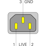
IEC 60320/C14 mains power inlet. Below is the pinout of this inlet
when looking into the male receptacle. Note that the PSU does not
have a wide-range input. It has to be configured
for either 115V or 230V AC.
➤ More
LIVE
In
115/230V AC 45-480 Hz 1
LIVE
In
115/230V AC 45-480 Hz 1
GND
-
Ground
Ensure that the PSU is configured for the correct mains voltage
before connecting the E-1800 to the mains. The configured voltage is
usually shown on a label just above the power inlet.
➤ More
Antenna input 10 kHz to 1.6 MHz
HT-1710
The RF unit (HT-1710) has two N-connectors that are used as the
antenna inputs: one for each frequency range. The lower socket
is for the 10 kHz to 1.6 MHz range. It is terminated at 50Ω.
This socket is also used when the RF unit is
configured for use with a single antenna.
➤ More
WARNING —
Never apply DC to the antenna input of the E-1800, as this will immediately
destroy the mixer transformers of the HT-1710 module.
These mixers are extremely difficult to find and replace. DC is applied, for example,
when the Bias tee (bias-T) of an active antenna is connected the wrong way around.
Demodulator output · FSK
DE-1710
The DE-1710 demodulator has a 6-pin DIN socket (BU2) on which the
demodulated output is available. This unfiltered signal is suitable
for connection to, say, a modem, such as the
ETM-1810/M.
Below is the pinout when looking into the socket.
Pins 1/3 provide a balanced signal.
AF
Out
AF line 600Ω (symmetric)
GND
-
Ground
AF
Out
AF line 600Ω (symmetric)
AF
In
AF input (for special cases)
CTRL
Out
Control voltage
MUTE
In
Muted when connected to GND (2)
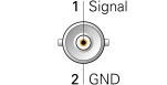
The DE-1710 demodulator also has a BNC socket on which
the 200 kHz intermediate frequency (IF2) is available
as a narrowband signal.
IF
Out
IF output, 200 kHz narrowband
GND
-
Ground
IF output
FU-1800
When the frequency converter FU-1800 is present, a converted
IF signal at 30 kHz or 525 kHz — selectable with a switch — is
available. It can be used for peripheral equipment, such as an external
FSK demodulator. The signal is available on a BNC socket (BU1).
IF
Out
IF output,30 kHz 525 kHz
GND
-
Ground
Also on the FU-1800 card is a 6-pin 240° DIN socket (BU2) on which
a balanced 600Ω AF signal is available at line level.
AF
Out
AF line 600Ω (symmetric)
GND
-
Ground
AF
Out
AF line 600Ω (symmetric)
-
-
unused
OSC
Out
325 kHz oscillator signal.
-
-
unused
Wideband output
BA-1700
When the optional BA-1700 wideband output card is fitted, a wideband 10.7 MHz
signal is available from its BNC socket. It can be used for the connection
of a panarama viewer.
WB
Out
10.7 MHz wideband signal
GND
-
Ground
Regular synthesizer
AO-1700
If the AO-1700 analyzer-oscillator is fitted in slot 9b
(rather than the SO-1800 fast synthesizer), there are
two BNC connectors with reference signals. The leftmost one (BU1)
is the 10 MHz reference input. It can be used to lock
the receiver to an external 10 MHz frequency standard. In is enabled
with the switch above it (S1) and accepts a level between -7 dBm and
+13 dBm into 50Ω.
10 MHz reference (BU1)
1.
REF
In
10 MHz reference (input/output)
2.
GND
-
Ground
The rightmost BNC socket (BU2) carries the signal from the Voltage
Controlled Oscillator (VCO), which varies between 42.2 and 72.2 MHz
at -7 dBm into 50Ω.
It is provided for measurement and service purposes only, and can be used
to verity the operation of the VCO inside the SO-1800.
VCO output (BU2)
1.
VCO
Out
?
2.
GND
-
Ground
Fast synthesizer
SO-1800/2
If the SO-1800 synthesizer-oscillator is fitted in slot 9b
(rather than the AO-1700 analyzer-oscillator), there are
three BNC connectors with reference signals. The leftmost one (BU1)
is the 10 MHz reference input/output. It can be used to lock
the receiver to an external 10 MHz frequency standard.
It accepts a level between -7 dBm and +13 dBm into 50Ω.
When used as an ouput, it delivers a 10 MHz signal from the
internal reference oscilator at -20 dBm into 50Ω.
10 MHz reference (BU1)
1.
REF
In/Out
10 MHz reference (input/output)
2.
GND
-
Ground
The rightmost BNC socket (BU2) carries the signal from the Voltage
Controlled Oscillator (VCO), which varies between 42.2 and 72.2 MHz
at -7 dBm into 50Ω.
It is provided for measurement and service purposes only, and can be used
to verity the operation of the VCO inside the SO-1800.
VCO output (BU2)
1.
VCO
Out
?
2.
GND
-
Ground
On the SO-1800/2, a third socket is present at the centre (BU3).
It provides an extra reference signal that is derived from the internal
10 MHz reference oscillator. The frequency of this extra signal is printed
on a label above BU3 (when present). In our case this is 100 kHz.
100 kHz output (BU3)
1.
100 kHz
Out
100 kHz output
2.
GND
-
Ground
External speaker
BU 602
When viewing the E-1800 from the rear, the socket at the bottom right is
for connection of an external speaker. This bus (BU 602) is fitted to the
main chassis and is visible through a hole in the rightmost panel,
which is usually one of the remote control interfaces (i.e. SER-1800).
When no remote interface is present, the vacant space is covered by a blank
panel with a hole through which BU 602 can be accessed.
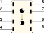
Below is the pinout when looking into the receptacle.
PWR
+12V DC
CTL
Control voltage A1-osc. ext.
REG
A1-osc. regulator
GND
Ground
LS1
Speaker (1)
LS2
Speaker (2)
The external speaker (max. 1 W) must be connected to pins 5 and 6.
ADo8 teleprinter socket
The TD-1710 and TZ-1710 plug-in cards are fitted
with a standard 8-pin ADo8 teleprinter socket, suitable for
connection of most single-current or double-current teleprinters.
TX and RX circuits are connected in series.
Below is the the pinout when looking into the socket.
a1
TX a
b1
Internally shorted to 3
a2
Internally shorted to 2
b2
RX b
n.c.
unused
n.c.
unused
n.c.
unused
GND
Ground
Teleprinter data output
TD-1702
The regular telegraphy demodulator (TD-1702/2) has a socket on which
the FSK (F1B) or FAX (F1C) data is available at TTL levels (0/5V).
The socket can also be used for connecting an external tuning indicator.
Below is the pinout when looking into the socket (BU1).
Δf
Out
210 · Δf
GND
-
Ground
Δf-A
Out
Analogue output for tuning indicator
DATA
Out
F1B/F1C afterLPF (TTL)
DATA
In
F1B/F1C (TTL) 1
+12V
Out
+12V/DC for tuning indicator
When shorting bridge 54-55 on PCB 52.1825.101.00 is open.
Teleprinter tone output (F≈)
TD-1710/2
For connection of an external device with a
tone interface,
such as a facsimile device, the TD-1710 is fitted with a
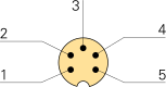
5-pin 240° DIN socket
on which a balanced version of the signal is available (pins 1-3).
The FSK (F1B) or FAX (F1C) data is also available as a balanced V.11 signal
(pins 4 and 5) and as a regular V.28 RS232 signal (pin 6).
Below is the pinout when looking into socket (BU2).
TONE
Out
Balanced 600Ω/0dBm
GND
-
Ground
TONE
Out
Balanced 600Ω/0dBm
DATA
Out
F1B/F1C data V.11 (-)
DATA
Out
F1B/F1C data V.11 (+)
DATA
Out
F1B/F1C data V.28
Teleprinter 2nd channel tone output (F≈)
TZ-1710/2
A similar output is available on the
TZ-1710/2 additional telegraphy demodulator.
It provides the data from the second channel (B-channel) in the case
of a two-channel F7B transmission (4-FSK).
Below is the pinout when looking into socket (BU2).
TONE
Out
Balanced 600Ω/0dBm
GND
-
Ground
TONE
Out
Balanced 600Ω/0dBm
DATA
Out
F7B data V.11 (-)
DATA
Out
F7B data V.11 (+)
DATA
Out
F7B data V.28
GPIB
IEC-1800
For remote control of the receiver it was ususally equipped with
an IEC-1800 plug in card, which provides an an IEE-488 interface,
also known as a IEC-625, GPIB or HPIB interface. It terminates in an
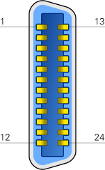
Amphenol 24-pin micro-ribbon connector. Below is the pinout
when looking into the socket.
DIO1
Data in/out bit 0
DIO2
Data in/out bit 1
DIO3
Data in/out bit 2
DIO4
Data in/out bit 3
EOI
End Or Identify
DAV
Data Valid
NRFD
Not Ready For Data
NDAC
Not Data Accepted
IFC
Interface Clear
SRQ
Service Request
ATN
Attention
Shield
Chassis
DIO5
Data in/out bit 4
DIO6
Data in/out bit 5
DIO7
Data in/out bit 6
DIO8
Data in/out bit 7
REN
Remote Enable
GND
Twisted wire with DAV
GND
Twisted wire with NRFD
GND
Twisted wire with NDAC
GND
Twisted wire with IFC
GND
Twisted wire with SRQ
GND
Twisted wire with ATN
GND
Logic ground
RS232 serial port
SER-1800
As an alternative to the above IEC-1800 card, the E-1800 could also
be equipped with the SER-1800 plug-in card, in which case the device
could be controlled from a computer via a standard V.24 (RS232) interface.
On old PC's, this is also known as the COM-port. On modern PCs,
a USB-to-RS232 adapter is required. Below is the pinout when looking
into the 25-pin DB25/S socket.
GND
Protective ground
TXD
Transmitted Data
RXD
Received Data
RTS
Request To Send
CTS
Clear To Send
DSR
Data Set Ready
GND
Signal ground
DCD
Data Carrier Detect
TXD+
RS422 TX (+)
ADR2
Control Address Bit 2
RXD+
RS422 RX (+)
IFC
Interface Selection 1
M/S
Master/Slave selection 2
ADR1
Control Address Bit 1
TCI
Transmitter Clock input
ADR3
Control Address Bit 3
RCI
Receiver Clock input
STOP
Stop
/RTS
Request To Send (inverted)
DTR
Data Terminal Ready
TXD-
RS422 TX (-)
ADR4
Control Address Bit 4
RXD-
RS422 RX (-)
TCO
Transmitter Clock Output
-
unused
IFC (pin 12) selects which interface is used: open = RS232,
shorted to ground = RS422.
When configured for RS422, M/S (pin 13) selects the role:
open = Slave, shorted to ground = Master.
Note that the pinout is different from the
V.24 standard, but
the common RS232 signals are at the expected pins.
Six pins (10, 14, 16, 18, 19, 22) are at TTL level. Pin 10, 14, 16 and 22
are for passing the control address.
Pins 9, 11, 21 and 23 are used for an RS422 interface
shown in blue
,
which can be activated by shorting pin 12 to ground.
This deactivates the RS232 interface.
When connecting the receiver to a modem, pins 9, 10, 11, 12, 13, 14, 16, 18,
21, 22 and 23 should not be wired, as the meaning of these pins has been
altered. Do not use a regular modem cable.
Parallel interface
PSE-1800
As an alternative to the IEC-1800 and SER-1800 interfaces,
the E-1800 can also be controlled by means of the proprietary PSE-1800 parallel bus.
The interface is installed as a plug-in card directly on the CPU board and runs
to the rear panel by means of a flat cable that is terminated in a
DD50 socket fitted in slot 11.
Note that the signals are similar (but not identical) to the signals on the
periperal bus of the SR-1810 memory card.
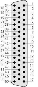
Below is the pinout when looking into the socket.
1.
CMD input
26.
1 kHz bit C
2.
CMD output
27.
1 kHz bit A
3.
Ctrl data
28.
10 kHz bit C
4.
+5V
29.
10 kHz bit A
5.
10 Hz bit A
30.
100 kHz bit B
6.
10 Hz bit C 1
31.
1 MHz bit D 1
7.
100 Hz bit D 1
32.
1 MHz bit C 1
8.
100 Hz bit B 1
33.
10 MHz bit B 1
9.
1 kHz bit D 1
34.
0V (GND)
10.
1 kHz bit B 1
35.
-
11.
10 kHz bit D 1
36.
-
12.
10 kHz bit B 1
37.
-
13.
100 kHz bit D 1
38.
-
14.
100 kHz bit C 1
39.
-
15.
100 kHz bit A 1
40.
-
16.
1 MHz bit B 1
41.
-
17.
1 MHz bit A 1
42.
-
18.
-
43.
-
19.
-
44.
Mode bit C
20.
-
45.
Mode bit B
21.
-
46.
Mode bit A
22.
10 Hz bit B
47.
Bandwidth bit A
23.
10 Hz bit D
48.
bandwidth bit B
24.
100 Hz bit C
49.
Bandwidth bit C
25.
100 Hz bit A
50.
10 MHz bit A
Peripheral bus
SR-1810
The SR-1810 memory card (part of the AO-1700 or SO-1800
assembly in slot 9b) holds a 50-pin
DD50/S connector that can be used
for the connection of peripheral equipment such as a
panorama viewer
or an automatic antenna switcher. Below is the pinout when looking into
the socket.
1.
100 Hz bit C 1
26.
1 kHz bit C 1
2.
10 Hz bit B 1
27.
1 kHz bit A 1
3.
10 Hz bit D 1
28.
10 kHz bit C 1
4.
+5V
29.
10 kHz bit A 1
5.
10 Hz bit A 1
30.
100 kHz bit B 1
6.
10 Hz bit C 1
31.
1 MHz bit D 1
7.
100 Hz bit D 1
32.
1 MHz bit C 1
8.
100 Hz bit B 1
33.
10 MHz bit B 1
9.
1 kHz bit D 1
34.
0V (GND)
10.
1 kHz bit B 1
35.
-
11.
10 kHz bit D 1
36.
SD Out
12.
10 kHz bit B 1
37.
COR relay
13.
100 kHz bit D 1
38.
-
14.
100 kHz bit C 1
39.
IN DAT 7
15.
100 kHz bit A 1
40.
IN DAT 6
16.
1 MHz bit B 1
41.
IN DAT 5
17.
1 MHz bit A 1
42.
IN CTRL PSG 2
18.
100 Hz bit A 1
43.
-
19.
-
44.
Ant. sw. 8 bit D
20.
-
45.
Ant. sw. 7 bit C
21.
/Strobe F 1
46.
Ant. sw. 6 bit B
22.
Ant. sw. 5 bit D
47.
Ant. sw. 5 bit A (LSB)
23.
Ant. sw. 3 bit C
48.
/Strobe A 3
24.
Ant. sw. 2 bit B
49.
COR relay
25.
Ant. sw. 1 bit A (LSB)
50.
10 MHz bit A 1
This signal is specifically for a panorama viewer
(e.g. PSG-1800).
LOW when PSG-1800 is in store mode (cursor),
and HIGH when it is in normal mode (no cursor).
/Strobe A goes low when sending data for the antenna switcher.
When using an antenna switcher, two different selection systems
are possible: 1 of 8 or 1 of 100. When using 1 of 8,
each of the 8 antenna selection lines (22-25 and 44-47) can be
driven low to directly select one of the eight antennas.
The other lines must remain high.
When using 1 of 100, up to 100 antennas can be connected.
In this case pins 22-25 (ABCD) are used for the units (×1), whilst pins
44-47 are used for the decades (×10) in BCD-format (i.e. 2 × 4 bits).
➤ More
Configuration
Antenna input
HT-1710
The E-1800 has two antenna inputs:
one for the 10 kHz to 1.6 MHz range,
and one for the 1.6 MHz to 30 MHz range. By default, two separate antennas
must be used. By altering a solder strap inside the
HT-1710 front end, the two inputs can be combined. The drawing below shows
the position of the solder strap in the compartment closest to the panel with
the two N-sockets. By default, the strap is in the 2/3 position, in which
case two antenna's must be used to cover the entire frequency range.
When the strap is in the 3/4 position, the upper antenna socket is disabled
and the antenna must be connected to the lower socket marked
(10 kHz - 1.6 MHz).
Solder strap inside the HT-1710 module
WARNING —
Never apply DC to the antenna input of the E-1800, as this will immediately
destroy the mixer transformers in the font-end of the HT-1710 module.
These mixers are extremely difficult to find and replace. DC is applied, for example,
when the Bias tee (bias-T) of an active antenna is connected the wrong way around.
It is possible to connect an antenna selector to the peripheral bus
on the SR-1810 or SR-1810/3 memory card. When such a switcher
is present, the desired antenna can be selected by pressing the ANT-button
followed by a 2-digit number and EXE (ENTER). There are two addressing modes:
1 of 8
In this mode, each of the eight address lines directly selects one of the
eight antennas. This is also known as linear mode. It is selected by setting
jumper BU3 on the SR-1810 to the a/b position.
1 of 100
In this mode it is possible to connect up to 100 antenas.
The eight address lines are used to compose a 2-digit
number in the range 1 to 100 in BCD-format. The lower 4 bits are
used for the units, whilst the upper 4 bits are used for the tens.
This mode is selected by setting jumper BU3 to the b/c position.
Mains voltage selection
NS-1800
Ensure that the NS-1800 is configured for the correct mains voltage
before connecting the E-1800 to the mains. This is particularly necessary
as many of the devices that appear on auction sites like eBay, are
configured for 115V rather than the more common 230V, even if they were
used by the German Army (Bundeswehr). The voltage is usually
shown on a label above the inlet.
Although it is perfectly possible to power the E-1800 via a VARIAC that
has been set to 115V, mistakes are easily made and it would be better to
find a more permanent solution.
Luckily, the PSU can easily be configured for the desired voltage, by
altering a solder strap inside the PSU.
The description below is for the NS-1800 PSU. Remove the PSU
from the receiver.
Then remove the cover from the left side of the PSU.
Locate the three terminals with the solder strap, which are located in the
upper corner, close to the rear panel, as shown in the image on the right.
In the image above, the de solder strap is fitted between the leftmost two
terminals, marked 110V. Move this strap to the rightmost two terminals,
marked 220V. That's all! Now that the PSU is open, take the time
to check the quality of the electrolytic capacitors. If they are bulging
out somewhat, you may want to replace them, as described above in the
section Restoration.
Solder strap inside the NS-1800 module
WARNING — Inside the PSU are dangerously high voltages that are
potentially lethal. Always disconnect the PSU from the mains before
opening it. Also be aware of high voltages that may be present at the
contacts of charged capacitors. Only open the PSU and carry out the
above modification if you know exactly what you are doing.
Below is an overview of the various mechanical filters that can be installed
on the FI-1710 filter module. The module has space for a maximum
of 7 filters, selectable from the list below. Two slots (6 and 7) are reserved for
USB and LSB.
The filters marked with a ✔ are installed by default.
The filters were extremely expensive.
In 1995, the price for a single filter was DM 850 (EUR 425).
A pair of high-precision matched ± 3.4 kHz Link 4 filters even cost
DM 2800 (EUR 1400) [4].
Bandwidth
Part. no.
R1 2
R2 2
R3 2
Filter
↔
Remark
Pos
100 Hz
52.1718.400.00
8k2
390
7k5
FZ230
A
1
150 Hz
52.1718.401.00
4k7
560
7k5
FZ231
A
1-2
300 Hz
52.1718.410.00
3k
820
7k5
FZ241
A
1-3
✔
600 Hz
52.1718.420.00
2k
1k5
33k
FZ250
A
1-4
1 kHz
52.1718.431.00
2k4
1k
7k5
FZ261
B
1-5
1.5 kHz
52.1718.430.00
2k
1k
7k5
FZ260
B
1-5
✔
1.5 kHz
52.1718.432.00
2k
1k
7k5
FZ2600
A
Search filter 3
1-5
3 kHz
52.1718.440.00
2k
10
1k6
FZ271
B
1-5
3 kHz
52.1718.441.00
2k
10
1k6
FZ276
A
Search filter 3
1-5
5 kHz
52.1718.451.00
2k
1k5
33k
FZ273
B
1-5
6 kHz
52.1718.450.00
2k
1k5
33k
FZ281
B
1-5
Single side band filters
-3 kHz
52.1717.460.00
2k
10
1k6
FE213
B
LSB
7
✔
-3.4 kHz
52.1718.461.00
2k
10
1k6
FE210
B
LSB
7
-3.4 kHz
51.1718.462.00
2k
10
1k6
FE214
A
LSB, Data, Link 4
7
+3 kHz
52.1718.470.00
2k
10
1k6
FE223
B
USB
6
✔
+3.4 kHz
52.1718.471.00
2k
10
1k6
FE220
B
USB
6
+3.4 kHz
52.1718.472.00
2k
10
1k6
FE224
A
USB, Data, Link 4
6
Specials
+2.7 kHz
52.1718.480.00
2k
10
1k6
FE226
B
USB6
6
-2.7 kHz
52.1718.481.00
2k
10
1k6
FE216
B
LSB6
7
The diagram above shows the positions of the seven selected filters on
the FI-1710 filter module. The filters should be installed in
slots 1 to 4 (upwards), with increasing bandwidth. The upper two slots
(6 and 7) are reserved for the USB and LSB filters respectively.
Each filter consists of a narrow PCB with a mechanical filter
and several small parts (resistors and capacitors).
Note that the actual filter comes in two sizes.
The shorter filters (A) are 88 mm long, whilst the longer ones (B) are 120 mm.
This is reflected by the A and B in the ↔ column in the table above.
Each filter is mounted on a narrow PCB with a 6-pin socket that mates with a 6-pin
header on the FI-1710 module. The PCB is fixated with two screws.
The diagram below shows the circuit diagram of a single filter unit.
Parts C1' and C2' are not always present.
See also the notes below.
Values of (C1+C1') and (C2+C2') are according to filter marking.
Values of R1, R2 and R2 as listed in the table above.
These resistors are used by the E-1800 to recognise/identify an installed
filter in a particular position.
Used in conjuction with programming functions Pr01 and Pr11.
Search filters have very low amplitude and group delay differences, and are
suitable for fast search tasks and for demodulating fast data transmission
modes.
Link = Link 11 (according to MIL-STD-6011, also known as
TADIL-A).
Needs a pair of LSB and USB filters.
These ± 3.4 kHz filters are highly accurate and have very low amplitude and
group delay differences. For proper operation, both filters must be present
in positions 6 (USB) and 7 (LSB) respectively.
The bridge between pins 3 and 4 is used by the E-1800 to sense the presence
of the filter.
In the first release of the FI-1710 manual, the ±2.7 kHz
USB/LSB filters are erroneously listed as ± 2.4 kHz.
IF-filters: 26 steep filters for carrier and sideband operation
Data-processing: 16 phase-optimized filters for high-speed digital data
Passband: Asymmetrical filter, ±5000Hz
Low phase noise synthesizer
Branding
Due to the fact that AEG Telefunken
changed hands a number of times,
the receiver was branded accordingly each time the company changed its name.
The following names may appear on the front panel of the receiver,
or on the accompanying brochures and documentation:


 = in Crypto Museum collection
 = documentation available