HX-20, also known as HC-20, was the world's first laptop computer,
released in 1982 by Seiko Epson 1 in Japan [1].
It didn't become very popular in the emerging homecomputer market of the 1980s,
but did find its way into a number of professional applications and turn-key
solutions.
The device has a footprint roughly the size of a piece of A4 paper and weighs
1.6 kg. It has a full size keyboard, a built-in 120 × 32 pixel LCD screen,
a small dot-matrix printer, and a microcassette recorder for storing
programs and data.
The device runs on two Hitachi HD6301 2 8-bit single-chip microcomputer units
(MCU), each of which holds a CPU, on-chip RAM, ROM, parallel I/O,
serial communications interface (SCI) and timers. One is the mainCPU,
whilst the other is the slave. Both processors run at 614 kHz.
The device also has a 4-octave sound generator.
The concept for the HX-20 was developed in July 1980 by Yokio Yokozawa at
Suwa Seikosha (today known as Seiko Epson), at which time a patent was
filed [I]. A patent for the enclosure design was filed in November
1982 by Masaki Kurihara on behalf of Epson [II].
The HX-20 was announced in Japan in 1981 as the HC-20, and was first shown in
North America as the HX-20 at the COMDEX 1981 show in Las Vegas.
It was officially launched the following year in July 1982.
Although the HX-20 was not widely accepted in the home computer market, largely
because of lack of add-ons and software titles, it became a popular device in
machine control and turn-key solutions. A large number of HX-20 units were used
for artillery by the German Air Force (Luftwaffe). The design of the later
Tandy TRS-80 Model 100, introduced in 1983 and much more popular in the
United States, is thought to be largely based on the design of the HX-20 [5].
HX-20 in espionage
It is little known that the repressive intelligence service of the former
DDR (East-Germany) — the Stasi
(MfS) — used the HX-20 in 1988 as a controller for its secret
cross-border communication network 'GRENZE' (Border).
The HX-20 was chosen because it was small, consumed little power
and could be purchased and used unobtrusively in Western countries.
The program for controlling the agent transmitter was stored on a
microcassette.
Production of GRENZE
started in early 1989, but due to the
Fall of the Berlin Wall
in November of that year, it was never deployed.
The image below provides an overview of the features of the HX-20.
The device has the size of an A4 sheet of paper and is approx. 4.5 cm high.
As it fits a regular attaché case, it was the ideal companion for business
men on the move.
It features a full-size keyboard, with four additional cursor control keys,
five function keys and three special keys. Above the keyboard is a 120 × 32
pixel liquid crystal display that can display 4 lines of
20 characters each. There is also a 57 mm wide ticket printer and an (optional)
microcassette device for storage of data and programs.
At the rear are connections for the battery charger, a reguar
RS232C serial port and a high-speed serial port.
The latter can be used for a video display unit or a floppy disk drive.
At the right side are the jack sockets of the audio interface, a reset button,
the on/off switch and the contrast adjustment of the LCD.
After power ON, the display offers the choice between
(1) MONITOR and (2) BASIC. MONITOR privides direct access to the memory,
whilst BASIC gives access to the built-in Microsoft BASIC interpreter.
Programs can be written in BASIC or in 6801 assembler.
Power consumption
Most of the device – including the two processors and the memory –
is constructed with CMOS technology. This results in a very low
power consumption that is proportional to the clock speed. At the chosen
clock speed of 614 kHz, the device can therefore run up to 50 hours from
a single charge of the internal NiCd battery pack. Of course this will
be less when the built-in printer and microcassette drive are used,
but it still allows many hours of uninterrupted operation.
Program storage
User programs can be stored/loaded in the following ways:
Micro Cassette Drive with microcassettes
Internal ROM socket (empty socket next to the BASIC ROMs)
External ROM cartridge (installed in place of the micro cassette drive)
TP-20 floppy disc drive (connected to high-speed serial port)
Models
HC-20
Japanese model with Katakana/Latin keyboard
HX-20
American/European model (with country variants)
Versions
Although there was only one model of the HX-20, there are several
keyboard layouts and character sets, each matching the requirements
for a specific country. Furthermore, some manufacturing
changes were made over time.
These differences are currently known:
The HX-20 comes with a grey or brown polypropylene (PP, plastic)
storage case that also has space for the accessories, supplies
and manuals. It has a grip at the top, allowing the computer to
be carried safely and dry when in transit.
Besides the computer, the case has dedicated slots for the micro
cassettes, printer paper rolls and the mains adapter/charger.
Computer
HX-20
The actual HX-20 computer is shown on the right.
In Japan it is known as HC-20. The computer can be expanded
internally by adding a ROM chip, or externally by connecting
peripheral devices to the serial interfaces at the rear, or to the
parallel docking connector at the left side.
The HX-20 was available in two colours: silver and cream.
Early prototypes were reportedly dark grey or even black.
Mains power adapter
The internal NiCd batteries can be charged with the supplied
mains power adapter. A full charging cycle takes approximately 8 hours,
after which the device must be unplugged from the mains in order to
prevent over-charging.
The device can be used when battery charging is in progress.
Once fully charged, the device can run from the internal batteries
for up to 50 hours, depending on the use of the cassette player,
the printer and connected peripherals.
Micro cassette drive
The HX-20 has an expansion bay at the rear right of the top surface.
This bay allows easy installation of an expansion cartridge, such as
the Micro Cassette Drive shown on the right.
Initially, the cassette drive was an option, but it was later supplied
as a standard pre-installed item. The drive accepts
standard microcassettes which were also used with the Olympus
pocket memo recorders of the era [4].
Microcassette
Programs written in 6801 assembler or BASIC could be stored on the
built-in micro cassette drive, which uses microcassettes as
the storage medium. Alternatively, an external floppy disc drive was
available as an add-on option.
The microcassette format was introduced in 1969 by Olympus, and was
often used for (analogue audio) pocket memo recorders [4]. It should
not be confused with the similar (but incompatible) mini-cassette
from Philips.
Print paper
The HX-20 features a built-in ticket printer to the left of the
display. It prints directly to a 57 mm wide roll of regular paper
and produces a more durable print than a regular thermal ticket
printer. For this, it requires a special ink ribbon cartridge that
could be obtained from EPSON.
Standard 57 mm wide paper rolls are widely available, although the roll
will be generally be too thick for the HX-20. It can simply be wound
manually onto an empty core.
Ink ribbon
The image on the right shows the miniature ink ribbon
cartridge for the built-in ticket printer.
This is a standard part that is also used in other
non-thermal EPSON ticket printers (ERC-09 B).
Below is the internal block diagram of the Hitachi HD6301 Microcomputer
Unit (MCU). The Epson HX-20 has two such processors, that are used as
master and slave respectively. Each MCU consists of a
Central Processing Unit (CPU), parallel I/O ports, a high-speed
Serial Communication Interface (SCI), several timers,
128 bytes RAM and 4 KB masked ROM. It has 8 different modes of
operation (0-7), determined by the state of P20, P21 and P22 immediately
after a reset (MODE).
The mainMCU starts up in mode 4, which means it can address external
RAM and ROM. The slaveMCU runs in mode 7, which is known as
the single chip mode. This means that
it only has access to the internal RAM (128 bytes) and ROM (4 KB).
The ROM contains firmware for serial communication with the main MCU
and for driving its parallel ports under control of the main MCU.
The masked ROM is 'programmed' at manufacturing time. For this reason, the two MCUs
each have a different part number — main MCU: C63010CA, slave MCU:
C63010CB.
Below is the block diagram of the HX-20, which shows its dual-MCU architecture.
At the left are the two MCU's: the main one at the top and the slave at
the bottom, both running at 614 kHz.
The mainMCU is responsible for the the memory bus, which is
connected to the RAM, ROM, real time clock (RTC), keyboard, liquid crystal
display (LCD) and the RAM/ROM expansion bus.
The slaveMCU is configured as general purpose I/O (GPIO), and acts
merely as an I/O expander.
The two MCUs are interconnected by means of a high-speed serial bus running at
34,800 baud. This bus is shared with the fast serial port that is available on
the 5-pin DIN socket at the rear of the computer.
It is used for the connection of a video display unit (VDU) and up to four
external TF-20 floppy disk drives.
The rest of the interfaces are divided over the two MCUs, but note that some
interfaces – in particular the ones with complex signals – are connected to both
processors.
The slaveMCU is responsible for power control (PSU), microcassette
drive, buzzer, audio interface and partly for the other interfaces as well.
The items shown in blue are internal parts, whilst the yellow items are external
options. The regular RS232 serial port on the 8-pin DIN socket
can be used for variety of devices, including a printer, CX-20 acoustic modem,
terminal and personal computer (PC).
The cartridge interface controls the microcassette drive, which can be
swapped for a ROM-cartridge. The audio interface can be used for an external
audio cassette recorder with start/stop control. It can be used for saving and
loading programs onto regular audio cassettes.
Main memory map
Below is the memory map of the mainMCU that runs the user's program(s).
The total addressable memory space is 64 KB. The lower 16 KB holds the
internal RAM of which the lower 256 bytes — shown at the right —
are reserved for the internal registers, I/O select, real time clock (RTC)
and internal RAM (128 bytes). The rest of the 16 KB of external RAM is
available for user programs.
The upper 32 KB are taken by the four standard ROMs, consisting of
the Monitor ROM (0), the Utility ROM (1) and two ROMs with the
BASIC interpreter (2 and 3). ROM 4 is a spare 8 KB socket
(Option ROM). Below ROM 4 is an 8 KB slot (EXP) into which the expansion
socket is mapped. It allows 8 KB of memory to be mapped into the address
space 0x4000 - 0x6000. It can be expanded to 16 KB by taking the space
reserved for ROM 4 as well. The expansion unit also has space for two
ROMs. When present they will be mapped into the space that is normally
taken by the BASIC interpreter (ROMs 2 and 3). In the diagram above,
this is shown in the second column.
The highest 16 bytes in ROM 0 (0xFFF0 - 0xFFFF) hold the interrupt vector
table (8 entries), the highest of which (0xFFFE - 0xFFFF) hold the start
address. When the CPU is started, it jumps to the address specified at
this location, which is 0xE000 — the start of ROM 0.
Slave memory map
Below is the memory map of the slaveMCU. It is much simpler, as the
processor is configured in MODE 7, also known as the single chip mode.
In this mode, only the lower 256 bytes and the upper 4096 bytes of the 64 KB
addressable memory space are used. This means that the slave processor only
has access to its internal 128 bytes RAM and 4 KB ROM. The rest is not accessible.
The firmware of this processor – held in the 4 KB internal ROM – is
responsible for communication with the main processor — through its
high-speed serial port (SCI) — and for handling the inputs and outputs of its I/O
ports, under control of the main processor. It also handles the RX part and some
control lines of the regular RS232 port,
which is implemented entirely in software.
Interior
The HX-20 is housed in a plastic enclosure that consists of two case shells.
The upper case shell holds the keyboard and the display, whilst the lower
shell holds the main PCB (the motherboard).
The interior can be accessed by removing 6 crosshead screws from the
bottom, after which the
bottom case shell can be removed.
Note that the upper shell
is connected to the lower shell by means of three short flat cables.
Remove these cables carefully by
raising the plastic cradle first.
The device is extremely well built, especially when considering that it
was made in 1982, at a time when the first homecomputers were beginning
to appear on the market. The motherboard has a professional layout and
the choice of components is excellent. The same can be said about the
miniature printer and the Micro Cassette Drive, both of which were
also made by EPSON.
We found our HX-20 on eBay in November 2025. When it arrived, the batteries were
flat (as expected), but after charging it for half an hour, we were able to power
it up. The buzzer sounded a short beep (as expected) and the display showed the
expected items (
1 MONITOR, 2 BASIC
) followed by garbage. Selecting one of the
two options resulted in a
Trap!
error,
after which the machine appeared to be stuck.
In a first attempt to get it going, we took the device apart, unplugged the battery
pack, and removed and reseated the four BASICROMs and the two MCUs.
After this, the garbage on the display was gone, but the startup menu now showed
three items:
1 MONITOR, 2 BASIC, 3 BASIC
. Selecting option 2 (BASIC) did not
enter the BASIC interpreter as expected, but caused the device to hang completely.
After searching the internet for possible solutions, we decided to issue
a machine initialisation as suggested by [7]. This procedure is described below
and fixed all our problems. It is worth trying this before taking the device apart.
Initialisation procedure
After powering up, the buzzer beeps shortly and the display should show the following:
   CTRL/@ Initialize
   1 MONITOR
   2 BASIC
On the German version of the HX-20 (with doesn't have an @-sign), the display
reads:
   CTRL/§ Initialize
   1 MONITOR
   2 BASIC
Note that the @-sign (and the §-sign) are above the numbers, so SHIFT has to
be pressed as well.
If nothing is shown on the display, try adjusting the contrast with the
knob at the right side of the machine. Note that the contrast setting alters the
viewing angle of the display.
If the menu doesn't start BASIC, or displays garbage, or shows more than two
items, or exhibits strange behavior, press
CTRL-@
(
CTRL-§
on the
German version) to set the date and time, and clear the RAM. Note that you
can only do this directly after pressing RESET or MENU, so you may have to try
it a couple of times [7]. In our case, this fixed all issues.
BASIC now works correctly:
   EPSON BASIC V-1.0
   Copyright 1982 by
   Microsoft & Epson
   P1:         0 bytes
   >
The HX-20 has one DIP-switch consisting of 4 individual on/off switches,
located to the left of the ROM bank
and accessible via the large ROM
access panel at the bottom of the device. The switches are numbered 1 to 4.
The first three switches (1-3) define which keyboard layout is used, as shown
in the table below (0 = off, 1 = on). Switch 4 selects the startup
medium. The DIP-switch in the example below is set to German (101) and starts
from the BASICROM (0).
1
2
3
Country
4
Startup from
0
0
0
Spain
0
BASIC ROM
0
0
1
UK
1
Floppy drive
0
1
0
Sweden
0
1
1
France
0 = off
1
0
0
Italy
1 = on
1
0
1
Germany
1
1
0
Denmark
1
1
1
USA
Connections
Power
The power socket is located at the rear of the device, next to the two
serial ports. It is a regular power connector, but note that the
(-) terminal is at the centre and the (+) terminal is the outer ring.
This is the other way around as with most European devices.
The power socket is not intended for powering the device but rather for
charging the internal battery pack (8 hours max.).
Also note that the battery is part of the power circuit. It must be
present for correct operation.
GND
Ground (0V)
PWR
+6V DC
RS-232 serial port
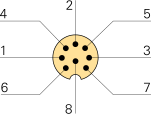
The HX-20 has a full RS-232 port with all modem signals, brought out on
an 8-pin DIN connector. The port offers a maximum speed of 4800 baud
and uses the 8N1 or 8N2 word format. Below is the pinout when looking into the socket
on the HX-20. Note that the cable shield should be connected to the shield
of the plug.
GND
Signal ground
TXD
Data out
RXD
Data in
RTS
Requent To Send
CTS
Clear To Send
DSR
Data Set Ready
DTR
Data Terminal Ready
CD
Carrier Detect
High speed serial port
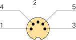
An additional high-speed serial port is available for connection
of an external video display unit (VDU) or a floppy disk drive.
The port has a fixed speed of 38.400 baud. The pinout of the
connector is given below. Note that the cable shield must be
connected to the shield of the plug.
GND
black
Signal ground
PTX
red
PRX
white
POUT
yellow
PIN
green
Connectors at the right side
At the right side of the device are four jack sockets, as shown in the
mage below. One of these is a 2.5 mm jack (REM). The others are all 3.5 mm.
MIC is a mono audio input. It can be used to load a program from an external
cassette recorder, or from a computer emulating such a device.
EAR is an output on which the 4-octave sound generator is available.
It can be used for storing programs on an external cassette recorder.
REM is an isolated relay contact that is closed when the externally
connected cassette recorder must start. BARCODE is further discussed below.
Barcode reader
The rearmost 3.5 mm jack socket at the right side of the device is
for connection of a barcode reader. Below is the pinout of this interface.
Note tat this is a one-way interface.
DATA
Data input
PWR
+5V DC
GND
Ground
Specifications
Device
Portable (notebook size) computer
Purpose
Personal computing, home, business, machine control
Model
HX-20 (HC-20)
Manufacturer
Seiko Epson
Year
1982
Country
Japan
Successor
PX-4
Processor
2 × Hitachi HD6301
Speed
614 kHz
OS
Proprietary (Monitor, BASIC)
RAM
16 KB (expandable to 32 KB)
ROM
32 KB (expanable to 64 KB)
Display
120 × 32 pixel LCD (4 lines × 20 chars)
Printer
Dot-matrix
Ink ribbon
ERC-09 B
Paper
57 mm wide (1¼)
Interfaces
1. RS232 serial port, 4,800 baud (modem, serial printer) 2. RS232 serial port, 38,400 baud (external floppy, video display) 3. Parallel port (docking connector)
Storage
Microcassette drive
Language
6801 Assembler, Microsoft Extended BASIC
Power
6V DC (4V needed to retain memory contents)
Battery
Rechargeable NiCd
Duration
≤ 50 hrs
Temperature
-5°C to +40°C
Storage
-20°C to +60°C
Dimensions
45 × 290 × 220 mm (HWD)
Weight
1600 g
Quantity
250,000
Price
USD 795 (1982)
Options
?
Micro Cassette Drive (USD 160)
H20EU
Expansion unit with 16 KB additional RAM
CX-20
300 baud acoustic coupler (modem)
TF-20
External floppy drive
?
Augmentative Communication Device (ACD) 'RealVoice'