


目录
背景介绍
作为带外管理手段,在日常监控及死机状态查询中具有一定作用,记录在此系列CPU中使用的案例。当系统发生死机,没有任何系统日志,无蓝屏信息等情况下通过PECI接口读取系统的各类寄存器,以发现问题所在。
命令字
linux下操作接口
命令字
int issue_peci_cmd(peci_cmd_t *pecicmd)
{
    int fd;
    int ioctl_ret;
    int retval = 0;
    //int i;

    fd = open(PECI_CTL_FILE, O_RDWR );
    if( fd == -1 )
	{
		printf ("Opening %s device failed\n",PECI_CTL_FILE);
        retval = -1;
	}
    else
    {

//        printf ("\nWrite_buffer : ");
 //       for (i = 0; i < pecicmd->write_len; i++)
 //       {
//            printf ("%x ", pecicmd->write_buffer[i]);
 //       }
 //       printf ("\n");


        ioctl_ret = ioctl(fd, (unsigned long)PECI_ISSUE_CMD, pecicmd);
        if( ioctl_ret == -1 )
            retval = -1;
    }
    (void)close(fd);

	if(pecicmd->status < 0)
		retval = -1;

    return(retval);
}
RdPkgConfig()
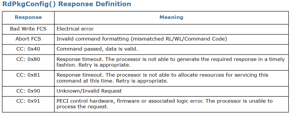
RdPkgConfig() 命令提供对处理器内部封装配置空间(PCS)的读取访问权限,该空间包含各种电源和热管理功能。处理器支持的典型 PCS 读取服务可包括访问温度数据、能耗状态、运行时间信息、DIMM 温度等。有关通过此命令支持的处理器具体服务的更多详细信息
The RdPkgConfig() format is as follows:
Write Length: 0x05
Read Length: 0x05 (DWord)
Command: 0xA1
代码实现
void rdpkgconfig(unsigned char index, unsigned short parameter)
{
	peci_rdpkgconfig_req_t req;
	peci_rdpkgconfig_res_t res;
	int ret;
	//unsigned char *p=&(res.data.peci_byte);
	unsigned char buff[10];


	memset(&res, 0, sizeof(res));

	req.host_id = 0x30;
	req.index = index;
	req.parameter = parameter;
	req.option = 4;  //4字节长度


	//ret = peci_cmd_rdpkgconfig(0xa1,req.host_id,&req, &res);
	ret = peci_cmd_rdpkgconfig(0xa1,req.host_id,&req, (peci_rdpkgconfig_res_t *)buff);

	if (ret <0 )
	{
		printf("rdpkgconfig Error, index 0x%x,parameter: 0x%x\n",  index, parameter);
	}

	else
	{
			#if 0 //bug, 读的数据为0
		printf("rdpkgconfig ok,  status  0x%x, index 0x%x,parameter: 0x%x, peci_dword 0x%x\n",
			res.completion_code, index, parameter, res.data.peci_byte);
			#endif

			#if 0
		printf("rdpkgconfig ok, status  0x%x, index 0x%x,parameter: 0x%x, peci_dword 0x%02x%02x%02x%02x\n",
				res.completion_code, index, parameter, p[4],p[3],p[2],p[1]);
			#endif

			#if 1
			if (buff[0] == 0x40)
			{
				printf("rdpkgconfig ok, index 0x%x,parameter: 0x%x, data: 0x%02x%02x%02x%02x\n",
					index, parameter, buff[4],buff[3],buff[2],buff[1]);
			}

			else
			{
				printf("rdpkgconfig fail, status	0x%x, index 0x%x,parameter: 0x%x\n",
					buff[0], index, parameter);
			}

			#endif
	}


}
应用案例
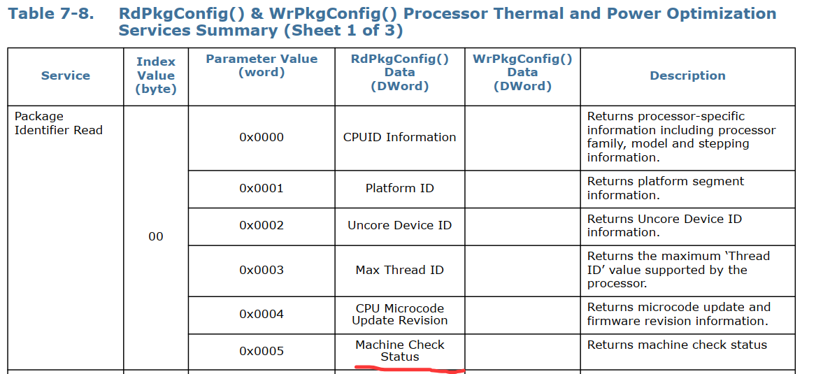
MCE读取
rdpkgconfig(0, 0x0005);
唤醒设备响应PECI
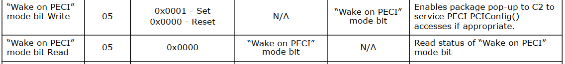
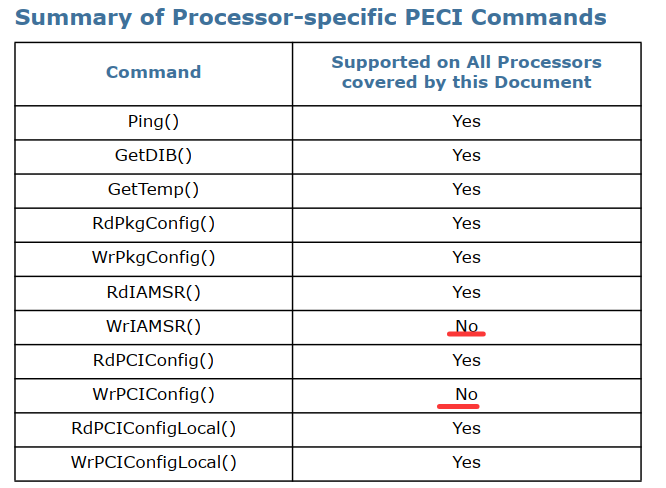
“设置‘Wake on PECI’模式位后,如果处理器处于低功耗状态,该位会强制将封装‘弹起’至 C2 状态来服务以下命令,从而使 WrPCIConfig()Local、RdPCIConfigLocal()、WrPCIConfig() 和 RdPCIConfig() 这些 PECI 命令能够成功完成。这种‘弹起’操作的确切功耗影响取决于产品 SKU、弹起起始的 C 状态以及协商的 PECI 比特率。对该位进行‘复位’或‘清零’,或者干脆不设置‘Wake on PECI’模式位,都可能导致处理器返回‘超时’响应(完成码为 0x82),表示服务该命令所需的资源正处于低功耗状态。
另外,也可以读取该模式位来确定 PECI 在封装 C3 或更深状态下的行为
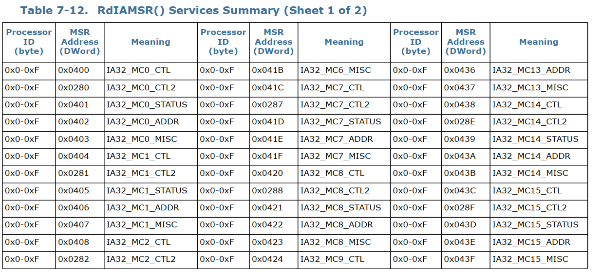
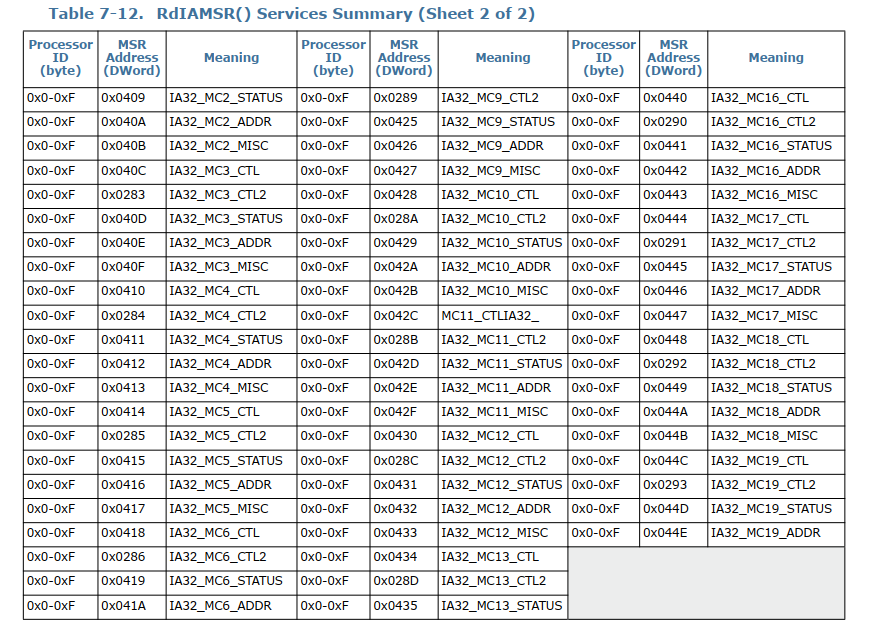
RdIAMSR()
Write Length: 0x05
Read Length: 0x02 (byte), 0x03 (word), 0x05 (DWord), 0x09 (QWord)
Command: 0xb1
代码实现
void RdIAMSR(unsigned char processor_id, unsigned short msr_addr)
{
	peci_rdiamsr_req_t req;
	//peci_rdiamsr_res_t res;
	int ret;
	unsigned char buff[10];


	req.host_id = 0x30;
	req.processor_id = processor_id;
	req.msr_addr = msr_addr;
	req.option = 8;  //4字节长度

	//ret = peci_cmd_rdiamsr(0xb1,req.host_id,&req, &res);
	ret = peci_cmd_rdiamsr(0xb1,req.host_id,&req, (peci_rdiamsr_res_t *)buff);

	if (ret <0 )
	{
		printf("RdIAMSR Error, processor_id 0x%x,msr_addr: 0x%x\n",  processor_id, msr_addr);
	}

	else
	{
		#if 0
		printf("RdIAMSR ok,  status  0x%x, processor_id 0x%x,msr_addr: 0x%x, peci_dword 0x%lx\n",
			res.completion_code, processor_id, msr_addr, res.data.peci_dword);
		#endif
		if (buff[0] == 0x40)
		{
			printf("RdIAMSR ok, processor_id 0x%x,msr_addr: 0x%x, data: 0x%02x%02x%02x%02x%02x%02x%02x%02x\n",
				processor_id, msr_addr, buff[8],buff[7],buff[6],buff[5],buff[4],buff[3],buff[2],buff[1]);
		}

		else
		{
			printf("RdIAMSR fail, status  0x%x, processor_id 0x%x,msr_addr: 0x%x\n",
				buff[0], processor_id, msr_addr);
		}
	}

}
RdPCIConfig()
RdPCIConfig() 命令提供对处理器外部下游设备中所维护的 PCI 配置空间的带外读取访问。有关所支持的设备、功能和寄存器的确切列表,请参见相应处理器数据手册第 2 卷中的相关章节(见‘相关文档’部分)。PECI 发起方可以通过与 BIOS 相同的方式发起读取操作,对该空间进行设备/功能/寄存器的枚举扫描。即使返回的是‘成功’完成码,全 1 的响应也可能表示该设备/功能/寄存器未实现。响应将遵循正常的 PCI 协议。
PCI 配置地址的构造如图 7-39 所示。在正常的带内流程中,总线编号用于将读/写操作导向正确的设备。对 Bus0、Device[0-7] 以及 Bus1、Device[8-15] 的所有访问都将被解码到处理器内部的寄存器,而其余访问则被解码到下游设备中的寄存器。
The RdPCIConfig() format is as follows:
Write Length: 0x06
Read Length: 0x05 (DWord)
Command: 0x61
RdPCIConfigLocal()
RdPCIConfigLocal() 命令提供对处理器内部 PCI 配置空间的带外读取访问。有关所支持的设备、功能和寄存器的确切列表,请参见相应处理器数据手册第 2 卷中的相关章节(见‘相关文档’部分)。PECI 发起方可以通过与 BIOS 相同的方式发起读取操作,对该空间进行设备/功能/寄存器的枚举扫描。即使返回的是‘成功’完成码,全 1 的响应也可能表示该设备/功能/寄存器未实现。PECI 发起方甚至在 BIOS 对系统总线进行枚举之前即可访问该空间。
PCI 配置地址的构造如图 7-41 所示。在正常的带内流程中,总线编号用于将读/写操作导向正确的设备。由于任何给定的客户端地址与总线编号之间都是一一对应的关系,因此使用错误总线编号发起的请求将被忽略,并且客户端将返回全 ‘0’ 以及一个‘成功’完成码。对 Bus0、Device[0-7] 以及 Bus1、Device[8-15] 的所有访问都将被解码到处理器内部的寄存器
Write Length: 0x05
Read Length: 0x02 (byte), 0x03 (word), 0x05 (DWord)
Command: 0xe1
代码实现
void RdPCIConfigLocal(unsigned char bus, unsigned char device, unsigned char function)
{
	peci_cmd_t cmd;


	unsigned char register_offset = 0;
	//uint32_t pci_addr = (bus << 20) | (device << 15) | (function << 12) | register_offset;

	uint32_t pci_addr = ((bus & 0xFF) << 20) | ((device & 0x1F) << 15) | ((function & 0x07) << 12) | (register_offset & 0xFFF);


	memset(&cmd, 0, sizeof(cmd));

	cmd.target = 0x30;			 // CPU 地址
	cmd.dev_id = 0xE1;			 // RdPCIConfigLocal 命令码


	// 1. 构造 5 字节请求体(小端序)
	cmd.write_buffer[0] = cmd.dev_id;  // Cmd Code
	cmd.write_buffer[1] = cmd.target;  // Host ID / Retry (target)
	cmd.write_buffer[2] = pci_addr & 0xFF;  //
	cmd.write_buffer[3] = (pci_addr>>8) & 0xFF;  //
	cmd.write_buffer[4] = (pci_addr>>16) & 0xFF;  //
	cmd.write_len = 5;			 // 固定 0x05


	// 2. 读取 5 字节(1字节 Completion Code + 4字节数据)
	cmd.read_len = 5;


	// 3. 发送并检查结果
	if (issue_peci_cmd_zh(&cmd) == 0) {
		if (cmd.read_buffer[0] == 0x40) {
			// cmd.read_buffer[0] 是 Completion Code 或其他头信息,需验证具体驱动实现
			// 数据通常从 read_buffer[1] 开始
			unsigned int vendor_device = (cmd.read_buffer[4] << 24) |
												 (cmd.read_buffer[3] << 16) |
												 (cmd.read_buffer[2] << 8)	|
												 cmd.read_buffer[1];
			printf("RdPCIConfigLocal ok: bus 0x%02x, device 0x%02x, function %d ,0x%08x\n",
						bus, device, function,vendor_device);


		//	printf("Vendor/Device ID: 0x%08x\n", vendor_device);
		//	printf("Vendor ID: 0x%04x\n", vendor_device & 0xFFFF);
		//	printf("Device ID: 0x%04x\n", vendor_device >> 16);

		}

		else
		{
			printf("RdPCIConfigLocal error, bus 0x%02x, device 0x%02x, function %d ,status 0x%x\n",
				  bus, device, function,cmd.read_buffer[0]);
		}

	}
	else
	{
		printf("RdPCIConfigLocal error2, bus 0x%02x, device 0x%02x, function %d ,status 0x%x\n",
			           bus, device, function,cmd.status);
	}

}
环境拓扑
lspci -vt
-[0000:00]-+-00.0  Intel Corporation 8th/9th Gen Core Processor Host Bridge / DRAM Registers
           +-01.0-[01]----00.0  Texas Instruments Device b005
           +-01.2-[02]----00.0  Device 4175:1024
           +-02.0  Intel Corporation CoffeeLake-H GT2 [UHD Graphics 630]
           +-08.0  Intel Corporation Xeon E3-1200 v5/v6 / E3-1500 v5 / 6th/7th/8th Gen Core Processor Gaussian Mixture Model
           +-12.0  Intel Corporation Cannon Lake PCH Thermal Controller
           +-14.0  Intel Corporation Cannon Lake PCH USB 3.1 xHCI Host Controller
           +-14.2  Intel Corporation Cannon Lake PCH Shared SRAM
           +-15.0  Intel Corporation Cannon Lake PCH Serial IO I2C Controller #0
           +-15.1  Intel Corporation Cannon Lake PCH Serial IO I2C Controller #1
           +-16.0  Intel Corporation Cannon Lake PCH HECI Controller
           +-17.0  Intel Corporation Cannon Lake Mobile PCH SATA AHCI Controller
           +-1b.0  Intel Corporation Cannon Lake PCH PCI Express Root Port #17
           +-1b.5-[04]----00.0  Device 4175:1042
           +-1b.7-[05]----00.0  Device 4175:1045
           +-1c.0  Intel Corporation Cannon Lake PCH PCI Express Root Port #1
           +-1c.4-[07]----00.0  Intel Corporation I211 Gigabit Network Connection
           +-1e.0  Intel Corporation Cannon Lake PCH Serial IO UART Host Controller
           +-1f.0  Intel Corporation CM246 Chipset LPC/eSPI Controller
           +-1f.3  Intel Corporation Cannon Lake PCH cAVS
           +-1f.4  Intel Corporation Cannon Lake PCH SMBus Controller
           \-1f.5  Intel Corporation Cannon Lake PCH SPI Controller
根据上述文档说明,我们读取0.1.0 和0.1.2 以及1b.0; 1b.5 ;1b.7;1c.0; 1c.4 这几个PCIE端口以及1 0 0;2 0 0这两个设备;
void read_pcie_root_port_info(unsigned char bus, unsigned char device, unsigned char function)
{
    peci_cmd_t cmd;
    unsigned char register_offset = 0;
    unsigned char cap_ptr = 0;
    unsigned char pcie_cap_offset = 0;
    unsigned int aer_cap_offset = 0;
    unsigned char offset, next_ptr;
    unsigned int ext_offset, next_ext_ptr;

    // 构造 PCI 配置地址
    uint32_t pci_addr = ((bus & 0xFF) << 20) | ((device & 0x1F) << 15) | ((function & 0x07) << 12) | (register_offset & 0xFFF);

    // ==================== 1. 读取 Vendor/Device ID (偏移 0x00) ====================
    memset(&cmd, 0, sizeof(cmd));
    cmd.target = 0x30;
    cmd.dev_id = 0xE1;  // RdPCIConfigLocal

    cmd.write_buffer[0] = cmd.dev_id;
    cmd.write_buffer[1] = cmd.target;
    cmd.write_buffer[2] = pci_addr & 0xFF;
    cmd.write_buffer[3] = (pci_addr >> 8) & 0xFF;
    cmd.write_buffer[4] = (pci_addr >> 16) & 0xFF;
    cmd.write_len = 5;
    cmd.read_len = 5;

    if (issue_peci_cmd_zh(&cmd) != 0) {
        printf("%02x  | %02x  | %02x    | PECI_ERR     | %02x  |              |          |\n",
               bus, device, function, cmd.status);
        return;
    }

    unsigned char cc = cmd.read_buffer[0];
    if (cc != 0x40) {
        printf("%02x  | %02x  | %02x    | FAIL_CC=%02x  | %02x  |              |          |\n",
               bus, device, function, cc, cc);
        return;
    }

    unsigned int vendor_device = (cmd.read_buffer[4] << 24) |
                                  (cmd.read_buffer[3] << 16) |
                                  (cmd.read_buffer[2] << 8)  |
                                  cmd.read_buffer[1];

    unsigned short vendor_id = vendor_device & 0xFFFF;
    unsigned short device_id = vendor_device >> 16;

    if (vendor_id == 0xFFFF || vendor_id == 0x0000) {
        return;
    }
00.1b.0正常读取
>>> Reading single PCIe device: 00:27.0 <<<
00  | 27  | 00    | 8086:1907 | 40  | 0x0000        | ? ?            | 0x00000000
其他PCH端口不能被读取
#

>>> Reading single PCIe device: 00:28.0 <<<
00  | 28  | 00    | FAIL_CC=90  | 90  |              |          |

#

>>> Reading single PCIe device: 00:28.4 <<<
00  | 28  | 04    | FAIL_CC=90  | 90  |              |          |

# .

>>> Reading single PCIe device: 00:27.0 <<<
00  | 27  | 00    | 8086:1907 | 40  | 0x0000        | ? ?            | 0x00000000

#

>>> Reading single PCIe device: 00:27.5 <<<
00  | 27  | 05    | FAIL_CC=90  | 90  |              |          |

#

>>> Reading single PCIe device: 00:27.7 <<<
00  | 27  | 07    | FAIL_CC=90  | 90  |              |          |
这几个PCH的没死机
00:01.0死机
以及00.1.2 这些CPU PEG端口
>>> Reading single PCIe device: 00:01.0 <<<这个 github项目
https://github.com/openbmc/peci-pcie
实际读取的 PCIe 配置空间地址是 有限且固定的,主要通过扫描 Bus 0 上的设备 1-31,读取每个 Function 的 Vendor/Device ID,然后通过 PCIe Capability 获取 Link Status。
总结
本文 记录了在host死机场景下,读取寄存器遇到的一些问题,并给出示例解决。后续进一步完善后再进行补充。
参考文档
Thermal Mechanical Specification and Design Guide.pdf
\intel IPDT\core-i7-lga-2011-guide.pdf
windows版本的lspci
Index of /download/linux/pci/windows
Intel® Core™ i7 Processor Family for the LGA-2011 Socket Datasheet, Volume 1 of 2


 被折叠的 条评论
为什么被折叠?
被折叠的 条评论
为什么被折叠?
 到【灌水乐园】发言


