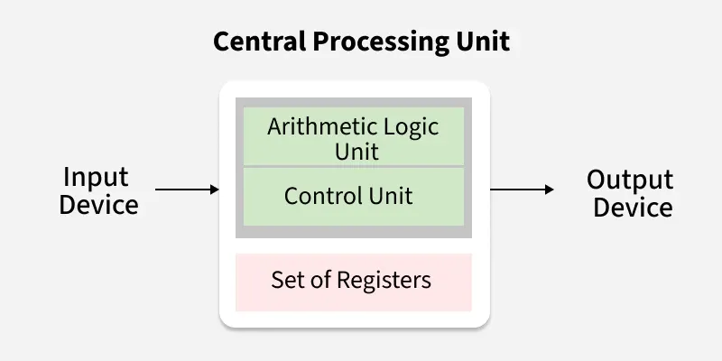
The Arithmetic Logic Unit (ALU) and the Data Path are core components that enable the CPU to execute instructions and manage data efficiently. These components work together with registers and buses to perform operations and move data across the system.
Arithmetic Logic Unit (ALU)
The ALU is a digital circuit within the CPU that performs arithmetic and logical operations. It takes input from registers, processes the data, and stores the result in a destination register or memory.
- Performs operations such as addition, subtraction, AND, OR, and NOT.
- Operates under the control of the control unit based on the instruction being executed.
Functions and Operations of ALU
1. Arithmetic Operations
ALU performs arithmetic operations to carry out basic mathematical calculations on binary numbers.
- Operations include addition, subtraction, increment, and decrement.
- Used during instruction execution for tasks like ADD, SUB, INC, and DEC.
2. Logical Operations
These operations manipulate data at the bit level using logic gates.
- Includes bitwise operations like AND, OR, XOR, and NOT.
- Essential for masking, setting, clearing, or toggling specific bits.
3. Shift Operations
ALU can shift bits left or right to aid in fast arithmetic and bit manipulation.
- Types include logical shift, arithmetic shift, and rotate operations.
- Often used for multiplication/division by powers of two and bit-level data formatting.
4. Comparison Operations
ALU supports comparison by evaluating two operands and setting appropriate flags.
- It checks for conditions like equality, greater than, or less than.
- Useful in branching and conditional instructions based on flag values.
5. Status Flag Generation
The ALU sets flags based on the result of operations to influence program control.
- Common flags: Zero (Z), Carry (C), Sign (S), Overflow (V).
- Flags are used in conditional execution and exception handling.
BUS
A bus is a communication system that transfers data between components inside or outside a computer. In the CPU, buses are used to carry data, addresses, and control signals between registers, ALU, and memory.
- Three main types: Data Bus, Address Bus, Control Bus.
- Shared pathway, so only one operation typically occurs at a time per bus.
Registers
Registers are small, fast storage elements inside the CPU used to temporarily hold data, addresses, or instructions. They are directly connected to the data path and ALU, enabling high-speed access.
- Common types include Accumulator, Program Counter, and General-Purpose Registers.
- Provide fast access compared to main memory.
Data Path
The Data Path consists of all hardware elements involved in data processing, including ALU, registers, and buses. It executes instructions by moving and transforming data based on control signals.
- Implements the actual operations of the CPU.
- Works with the control unit to execute instructions in steps.
One Bus Organization
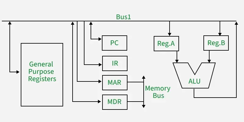
In a one-bus organization, a single bus is used for all data transfers among CPU components, including registers and the ALU. This design is simple and cost-effective but can lead to slower execution due to sequential operations.
- Only one data movement can occur at a time.
- Requires temporary registers for intermediate values during ALU operations.
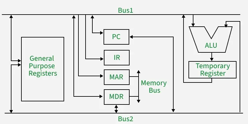
Two Bus Organization
The two-bus organization exists in two common versions, each optimizing data flow differently. Both versions use two buses but differ in how data is transferred between registers, the ALU, and memory.
Version 1: Standard Two-Bus with ALU Inputs
This version uses two separate input buses to feed operands directly into the ALU, allowing simultaneous access to two source registers. The ALU output is sent either to a common internal result bus (used for writing back data), or directly into a register, depending on the design.
- Improves speed by enabling parallel operand fetching into the ALU.
- Balances performance and hardware cost, often used in mid-level CPU designs.
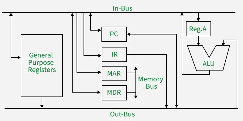
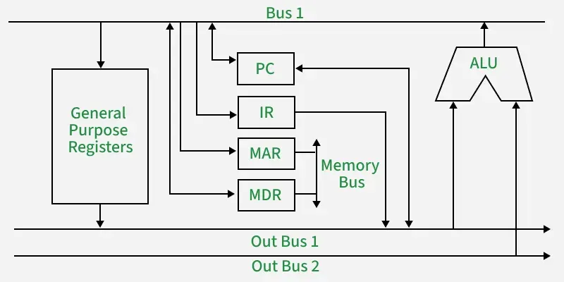
Version 2: Bus-In and Bus-Out Architecture
In this variation, two buses serve different roles: Bus-Out is used to send data from registers to the ALU or memory, while Bus-In is used to receive results into registers or memory. The ALU reads from Bus-Out and places results on Bus-In.
- Enables simultaneous read and write operations using separate buses for input and output.
- Simplifies design while supporting efficient internal data flow between components.
Three Bus Organization
A three-bus organization includes two buses for ALU input and a third bus for output, enabling all three data paths to be active in the same cycle. This results in faster instruction execution due to full parallelism.
- Allows reading two operands and writing a result in one clock cycle.
- Requires more hardware and control logic, increasing complexity and cost.
The main advantages of multiple bus organizations over the single bus are as given below.
- Increase in size of the registers.
- Reduction in the number of cycles for execution.
- Increases the speed of execution or we can say faster execution.
