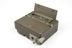
The SP-20 is a spy radio set,
developed around 1970 by
AEG Telefunken
and Pfitzner/Teletron in Germany,
as a replacement for the aging valve-based SP-15.
It was used by a number of
Stay-Behind Organizations in Europe (Gladio)
as well as by the Special Forces of the German Army.
The two versions can be determined by their colours – green and grey –
but are otherwise identical.
The image on the right shows part of the military version of the SP-20 as it was
used by German Special Forces (SF). All units are painted in the standard
NATO olive green colour.
It was often used with the RT-3 burst encoder.
The version used by stay-behind (Gladio)
was grey and was used with a variety of morse burst encoders.
Most surviving SP-20 units were found without a matching receiver.
Although the manufacturer developed a digital receiver for the
SP-20, only a limited quantity was built and it was never put into
large scale production. Instead, the old FE-8 receiver —
originally supplied with the SP-15 spy set — was used.
All units are housed in a similar case of approx. 155 x 105 x 32 mm,
except for the FE-8 receiver. A similar case was later used for the
Speicher burst encoder and the PSU.
A revised version of the SP-20 set was planned and partly developed in 1983
[A].
It was known as SP 20 neu (new) and also as P 928.
It consisted of the existing
transmitter and synthesizer, with a new KE-30 receiver and a KÜG
Kurzzeitübertragungsgerät (burst transmitter) with external
keyboard and display, but as far as we
know, the improved P-928 system was never released.
Although the FE-8 receiver
was not part of the SP-20 set itself,
it was issued with the set. In practice,
the FE-8 was
commonly re-issued from decomissioned
SP-15 radio sets.
Stay-Behind version
Special version for the secret
Stay-Behind Organisation, sometimes
referred to as Gladio,
that would activate themselves during the
Cold War in the event of a war between Europe and the USSR.
This version can be recognised by its grey enclosures.
Early stay-behind sets and prototypes were painted in dark grey,
whilst later units were bright grey [1].
SP-20 neu
Revised version of the SP-20, also known as Projekt 928 (P-928),
that was planned for release in 1983.
Although and handfull of prototypes
of the KE-30 receiver
were manufactured, the complete P-298 was never
released as it had been surpassed by the new
pan-European FS-5000
by the time it was ready.
Military version
The most common version of the SP-20 is the military variant, which can
be recognised by the olive green colour of its cases. Initially, the
military variant consisted of two modules (transmitter
and antenna tuner), and was crystal operated.
The two units were manufactured by
Telefunken.
The two units can be mounted together by means of a metal rail on the top
surface of the transmitter and a similar rail on the bottom surface of
the antenna tuner. The transmitter is connected to the antenna tuner by
means of a short coaxial cable with SMB plugs at either end.
The set was used in combination with the older Wandel & Goltermann
FE-8 (BN-48) receiver
that was also used with the earlier SP-15 radio set.
Initially, the transmitter was crystal-operated,
but the crystals were later replaced by
a digital frequency synthesizer manufactured by
Pfitzner.
The image above shows a complete military SP-20 set with
KS-30 synthesizer
and the older FE-8 receiver,
as it was used by German Special Forces (SF) during the Cold War. The unit
at the front is an RT-3 burst encoder. Suitable
webbing gear was supplied for transport of the radio station.
Stay-Behind version
wanted item
The Stay-Behind version of the SP-20 can be recognised by its grey enclosures.
The set is largely the same as the military variant but the units have a
mounting rail at either side of their body, so that they can be combined
horizontally. The set consisted of a transmitter
and an antenna tuner. Initially, a 1296 channel
analogue frequency synthesizer
was developed, but this was eventually abandoned as its operation was too
complex. Instead, single crystals were during the first years.
A Power Supply Unit (PSU) was available as an option. It was housed
in a similar enclosure and could also be used as a power inverter,
allowing the set to be powered by an alternative 6-24V DC power source,
or the 12V battery of a car. The battery could also be recharged by the PSU.
The set was later complemented by the new
KS-30 synthesizer that was developed by
Pfitzner.
The image on the right shows a complete SP-20 radio station in grey
stay-behind enclosures.
The rather rare PSU is visible at the left. At the left edge the later
MMP burst encoder is visible.
Note that with this version, the synthesizer is not connected to the
transmitter by means of a 1 metre shielded cable, but by means of a small
grey connector block, as shown above. In the image, all units are mounted
together by means of the sideways rails, except for the
antenna tuner
which is always mounted on top of the transmitter. Initially, this set
was supplied with the
Speicher burst encoder,
but this was later replaced by the much faster and more versatile
MMP.
Projekt 928
SP-20 neu
In the late 1970s, Pfitzner
started the development of the successor to
the SP-20 radio set, which was designated P-928. It was also known as
SP-20 neu (new). Based on the existing set, with a
new receiver and
a faster burst encoder,
the new system was planned for introduction in 1983.
But by the time the set was completed, orders had already
been given for the development of the flexible pan-European
FS-5000 system.
As a result, Pfitzner's P-928 set was never released.
The image on the right shows a KE-30 receiver with dark
front panel that was developed as part of the P-928 project [6].
It is housed in the same enclosure as the KS-30 synthesizer but only has
one 20-pin socket, that is located at the left.
The space at the right (on the synthesizer used for the 2nd socket),
is taken up by a LED bar which gives an indication of the received
signal strength. Although the receiver would probably have been a good
replacement for the aging FE-8 (BN-58),
it was never rolled out. There are
claims that the technical specifications of the KE-30 could not
compete with those of the FE-8.
In 1983, the planned P-928 set consisted of the following components [A]:
The S-6800 transmitter was developed by AEG Telefunken and is fully
transistorised.
It is both crystal and synthesizer operated and is suitable for
CW (morse) and FSK (frequency shift keying). The maximum ouput power
is 30W.
Note the two rigs on top of the unit, allowing it to be attached to
the ASG-6800 antenna tuner (see below).
The transmitter is also known as Sender SP-20.
The ASG-6800 antenna tuner was designed for use in combination with the
S-6800 transmitter. Like the transmitter, it was manufactured by AEG Telefunken
in the mid 1970s.
The tuner was connected to the transmitter by means of a short coaxial
cable with an SMB-connector at both ends.
At the bottom it has two rigs that allows it to be slotted onto the
S-6800 transmitter (see above).
Initially, an analogue frequency synthesizer was developed by AEG Telefunken,
as the driver for the S-6800 transmitter. Using 72 different quarz crystals,
divided over two banks, the unit offered a total of 1296 channels
(6 x 6 x 6 x 6).
As the unit was too cumbersome to operate — it wasn't possible to enter the
desired frequency directly — the design was eventually abandoned, in favour
of individual crystals for each channel.
Initially, the S-6800 transmitter was crystal operated. Later, an external
synthesizer unit (KS-30) was developed by
Pfitzner. This was probably early in 1983.
The sythesizer allows a frequency coverage of 2-24MHz in 1kHz steps.
It was added to all existing SP-20 stations and connected to the transmitter
via a multi-pin connector on the left. A rather long cable was supplied to
connect the KS-30 to the S-6800.
The SP-20 did not have a matching receiver. Instead the existing
FE-8 receiver
of the old SP-15 radio set
was re-used, probably because
of its excellent performance and reliability.
The FE-8, also known as the BN-58, had two frequency bands and
featured permeability tuning. As a result, it had linear frequency
scales that were calibrated in MHz rather than units.
In the late 1970s, Pfitzner
developed a new receiver for the SP-20.
It was digital, was housed in the same enclosure as the other units,
and was supposed to replace the old FE-8 receiver.
The new receiver was designated KE-30, but for several reasons it was never
taken into large-scale production.
With the military variant of the SP-20, it was common practice
to connect the synthesizer to the transmitter by means of
a one meter cable.
The image on the right shows a typical multi-cable as it was supplied
with the military SP-20 variant. The full wiring of this cable is given
on the KS-30 page.
Connection block
With the stay-behind version of the set however,
it was more common to place the synthesizer to the left of the transmitter
and connect the two units by means of the small connection block shown
in the image on the right [7].
Toolkit
Each SP-20 unit came with a set of spare parts, tools and accessories.
In most cases, these were packed in a sturdy 'lunch box' with a canvas
strap to prevent the contents from falling out.
The image on the right shows an example of such a toolbox. It contains
a screwdriver, pliers, insulation tape, ceramic antenna insulators, etc.
Antenna
The antenna tuner makes it possible to use virtually any type of antenna
with the S-8600 transmitter. In practice, a long antenna wire was used on most
occasions. The antenna, and a suitable ground, are connected to the left
side of the tuner, via 2 banana-type sockets.
The images below show some of the typical wire antennas that were supplied
with the SP-20. Please note that transmitter and receiver each needed a separate
antenna.
Webbing kit
When used by German Special Forces, the olive green SP-20 radio set
was usually carried in two plastic cases, attached to the webbing kit
of the radio operator. In theory it was possible to operate the radio
from within the carrying cases.
The image on the right shows the canvas webbing kit and the two plastic
cases.
In order to minimise the risk of interception and
radio direction finding (RDF),
a burst encoder
was often used with the SP-20.
It allows a pre-recorded coded message to be played
back in morse code
at very high speed, in order to keep the transmission as short as
possible.
RT-3
The first burst encoder that was issued with the SP-20 was this
electro-mechanical RT-3 unit.
A small military-grade metal box that allowed a message of no more than
25 characters to be stored mechanically. Once on-air, the message
was played back by operating a hand crank.
Later, more advanced burst encoders were issued, such as the
GRA-71,
MMP
and Speicher.
The Speicher (memory) was an electronic burst encoder
for sending numbers at high speed in
morse code. It was powered
directly from the mains and was housed in a similar case as the
units of the SP-20 spy radio set.
The Speicher was probably issued in the 1970s to replace the
rather limited RT-3.
Eventually it was replaced itself by the
more advanced MMP.
The MMP was a fully electronic high-speed (1200 baud) burst
encoder that was used with both the
SP-15 and the SP-20 spy sets.
The MMP replaced older devices, such as the mechanical
RT-3,
the American AN/GRA-71
and the early electronic Speicher.
It could hold more than 1000 letters and numbers in its battery-bakced
CMOS memory and could send them at various speeds between 15 and 1200 baud.
Initially, no technical documentation of the SP-20 was available,
but over the years, we've received contributions from a number of our
visitors. The documentation below, is what we have at the moment.
The circuit diagrams of the transmitter are incomplete. If you have
more complete documentation, or if you have other information that
might be useful, please contact us.
Crypto Museum is still looking for the grey stay-behind variant of
the SP-20 and would also like to add the KE-30 receiver to its
collection. If you have any of these available, or if you have any other
SP-20 related parts that are not yet shown here,
please contact us.









![Complete stay-behind version of the SP-20. Copyright Gerhard Reinel [5] WANTED ITEM](img/sp20_grau_large.jpg)
![KE-30 receiver is grey enclosure with dark front panel [6] WANTED ITEM](https://www.cryptomuseum.com/img/ke30_green_small.jpg)


![Connection block for fitting the KS-30 synthesizer directly to the S-6800 transmitter [7]](img/304077/000/full.jpg)